Honda Ridgeline. Manual - part 130


  Index      Honda     Honda Ridgeline - service repair manual 2006-2008 year


Search            


Content   ..  128  129  130  131   ..


Honda Ridgeline. Manual - part 130


08

09

10

YES

NO

YES

NO

11-284

Fuel Supply System

Fuel Pump Circuit Troubleshooting (cont’d)

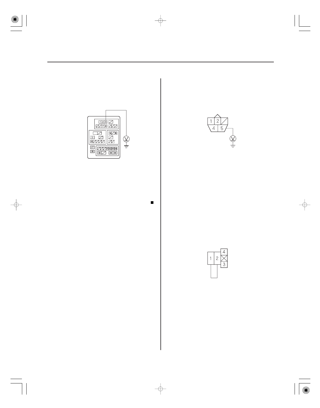
UNDER-DASH FUSE/RELAY BOX 39P CONNECTOR

IMOFPR
(GRN/WHT)

FUEL PUMP 5P CONNECTOR

FUEL PUMP
(YEL/GRN)

PGM-FI MAIN RELAY 2 (FUEL PUMP)
4P CONNECTOR

IG1

FUEL PUMP

JUMPER WIRE

19. Turn the ignition switch ON (II), and measure

voltage between under-dash fuse/relay box 39P
connector terminal No. 3 and body ground within
2 seconds.

Update the PCM if it does not have the latest

software (see page 11-7), or substitute a known-
good PCM (see page 11-8), then recheck. If the
symptom/indication goes away with a known-good
PCM, replace the original PCM (see page 11-205).

Go to step 20.

20. Turn the ignition switch OFF.

21. Remove the rear seat-backs (see page 20-119).

22. Remove the access panel from the floor.

23. Turn the ignition switch ON (II), and measure

voltage between fuel pump 5P connector terminal
No. 5 and body ground within 2 seconds.

Go to step 28.

Go to step 24.

24. Turn the ignition switch OFF.

25. Remove PGM-FI main relay 2 (FUEL PUMP).

26. Connect PGM-FI main relay 2 (FUEL PUMP) 4P

connector terminals No. 1 and No. 2 with a jumper
wire.

Wire side of female terminals

Wire side of female terminals

Terminal side of female terminals

Is ther e batter y voltage?

Is ther e batter y voltage?

01

02

YES

NO

YES

NO

11-285

FUEL TANK UNIT 5P CONNECTOR

FUEL PUMP
(YEL/GRN)

GND (BLK)

FUEL TANK UNIT 5P CONNECTOR

27. Turn the ignition switch ON (II), and measure

voltage between fuel tank unit 5P connector
terminal No. 5 and body ground within 2 seconds.

Replace PGM-FI main relay 2 (FUEL

PUMP).

Repair open in the wire between PGM-FI main

relay 2 (FUEL PUMP) and the fuel tank unit 5P
connector.

28. Turn the ignition switch OFF.

29. Check for continuity between fuel tank unit 5P

connector terminal No. 4 and body ground.

Replace the fuel pump.

Repair open in the wire between the fuel tank

unit 5P connector and G502.

Wire side of female terminals

Wire side of female terminals

Is ther e batter y voltage?

Is ther e continuity?

01

02

03

SJC8A00A20326400000MBAT00

With the HDS

11-286

Fuel Supply System

Fuel Pressure Relieving

A

A

A

B

C

E

D

Before disconnecting fuel lines or hoses, relieve
pressure from the system by stopping the fuel pump
and then disconnecting the fuel tube/quick connect
fitting in the engine compartment.

1. Make sure you have the anti-theft codes for the

audio system and the navigation system (if
equipped).

2. Remove the fuel fill cap, and relieve the pressure in

the fuel tank.

3. Turn the ignition switch ON (II).

4. From the INSPECTION MENU of the HDS, select

Fuel Pump OFF, then start the engine, and let it idle
until it stalls.

5. Turn the ignition switch OFF.

NOTE:

• Do not allow the engine to idle above 1,000 rpm

or the PCM will continue to operate the fuel
pump.

• A DTC or a Temporary DTC may be set during

this procedure. Check for DTCs, and clear them
as needed (see page 11-3).

6. Turn the ignition switch OFF.

7. Disconnect the negative cable from the battery.

8. Remove the quick-connect fitting cover (A).

9. Check the fuel quick-connect fitting for dirt, and

clean it if needed.

10. Place a rag or shop towel over the quick-connect

fitting (A).

11. Disconnect the quick-connect fitting (A): Hold the

connector (B) with one hand, and squeeze the
retainer tabs (C) with the other hand to release
them from the locking tabs (D). Pull the connector
off.

NOTE:

• Be careful not to damage the line (E) or other

parts.

• Do not use tools.
• If the connector does not move, keep the retainer

tabs pressed down, and alternately pull and push
the connector until it comes off easily.

• Do not remove the retainer from the line; once

removed, the retainer must be replaced with a
new one.

04

05

06

Without the HDS

11-287

A

A

A

12. After disconnecting the quick-connect fitting, check

it for dirt or damage (see step 4 on page 11-293).

13. Reconnect the negative cable to the battery, then

do this:

• Do the power window control unit reset

procedure (see page 22-209).

• Enter the anti-theft codes for the radio and the

navigation system (if equipped).

• Set the clock.

1. Make sure you have the anti-theft codes for the

audio system and the navigation system (if
equipped).

2. Remove the left kick panel (see page 20-60), then

remove PGM-Fl main relay 2 (FUEL PUMP) (A) from
the under-dash fuse/relay box.

3. Start the engine, and let it idle until it stalls.

NOTE: If any DTCs are stored, clear and ignore
them.

4. Turn the ignition switch OFF.

5. Remove the fuel fill cap.

6. Disconnect the negative cable from the battery.

7. Remove the quick-connect fitting cover (A).

8. Check the fuel quick-connect fitting for dirt, and

clean it if needed.

9. Place a rag or shop towel over the quick-connect

fitting (A).

(cont’d)


Content   ..  128  129  130  131   ..