Honda Ridgeline. Manual - part 129
03
04
*01
−
−
−
−
−
−
YES
NO
YES
NO
YES
NO
11-280
Fuel Supply System
DTC Troubleshooting (cont’d)
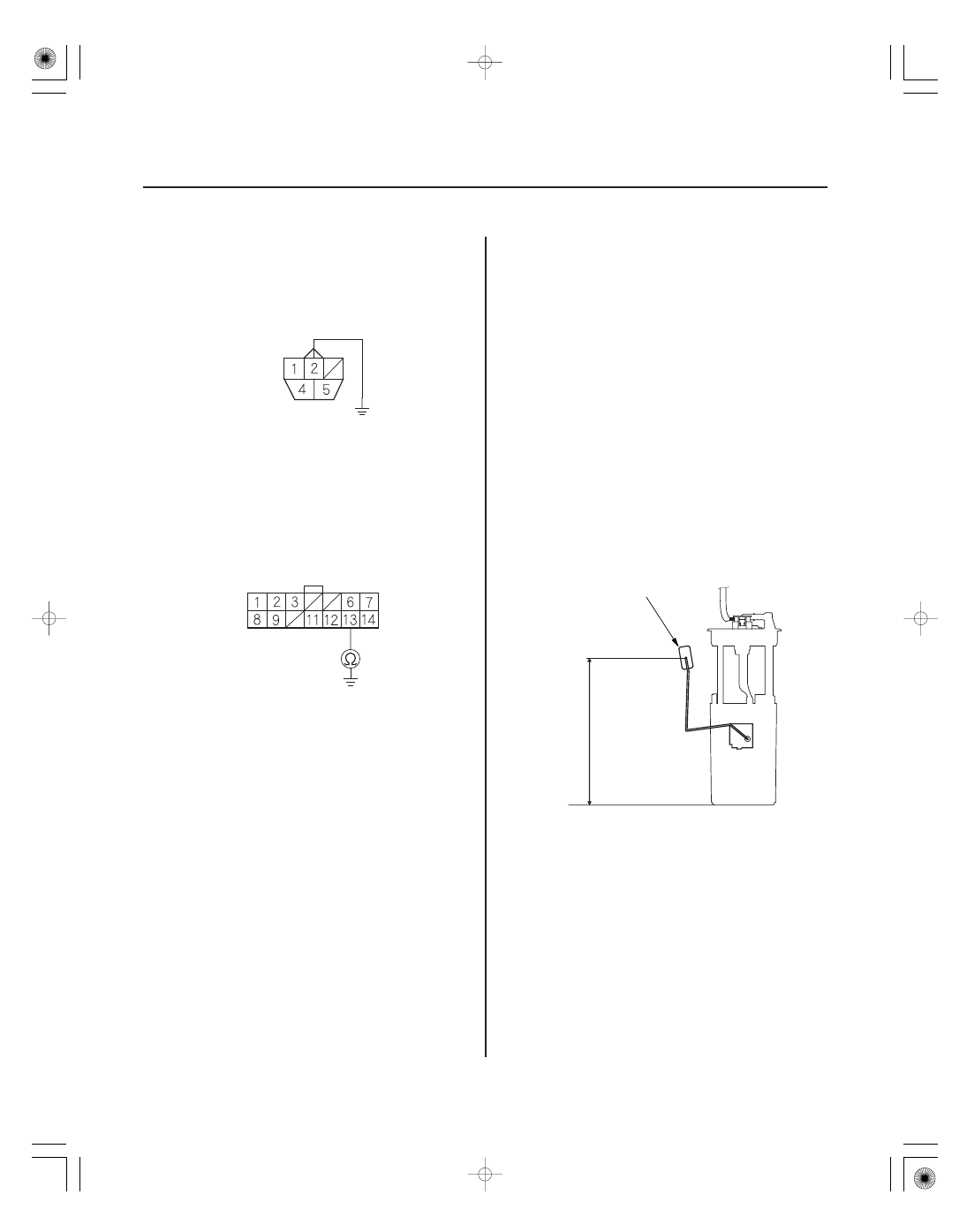
FUEL TANK UNIT 5P CONNECTOR
SIGNAL (YEL/BLK)
JUMPER WIRE
GAUGE CONTROL MODULE 14P CONNECTOR
SIGNAL (YEL/BLK)
F
9.6 in.
(243.3 mm)
A
12. Connect fuel tank unit 5P connector terminal No. 2
to body ground with a jumper wire.
13. Check for continuity between gauge control
module 14P connector terminal No. 13 and body
ground.
Go to step 14.
Repair open in the wire between the gauge
control module (signal line) and the fuel gauge
sending unit, then go to step 24.
14. Remove the jumper wire from the fuel tank unit 5P
connector.
15. Remove the fuel tank unit (see page 11-297).
16. Test the fuel gauge sending unit (see page 11-302).
Go to step 17.
Replace the fuel gauge sending unit (see page
11-300), then go to step 24.
17. Connect the fuel tank unit 5P connector.
18. Reconnect the gauge control module 14P connector.
19. Turn the ignition switch ON (II).
20. Clear the DTC with the HDS.
21. Set the float (A) to the F position.
22. Check the fuel gauge.
Go to step 30.
Replace the gauge control module (see page
22-263), then go to step 24.
Wire side of female terminals
Wire side of female terminals
Is ther e continuity?
Is the f uel gauge sending unit OK ?
Does the gauge move to the f ull position?