Honda Ridgeline. Manual - part 106
06
07
08
−
−
−
−
YES
NO
YES
NO
11-188
PGM-FI System
MIL Circuit Troubleshooting (cont’d)
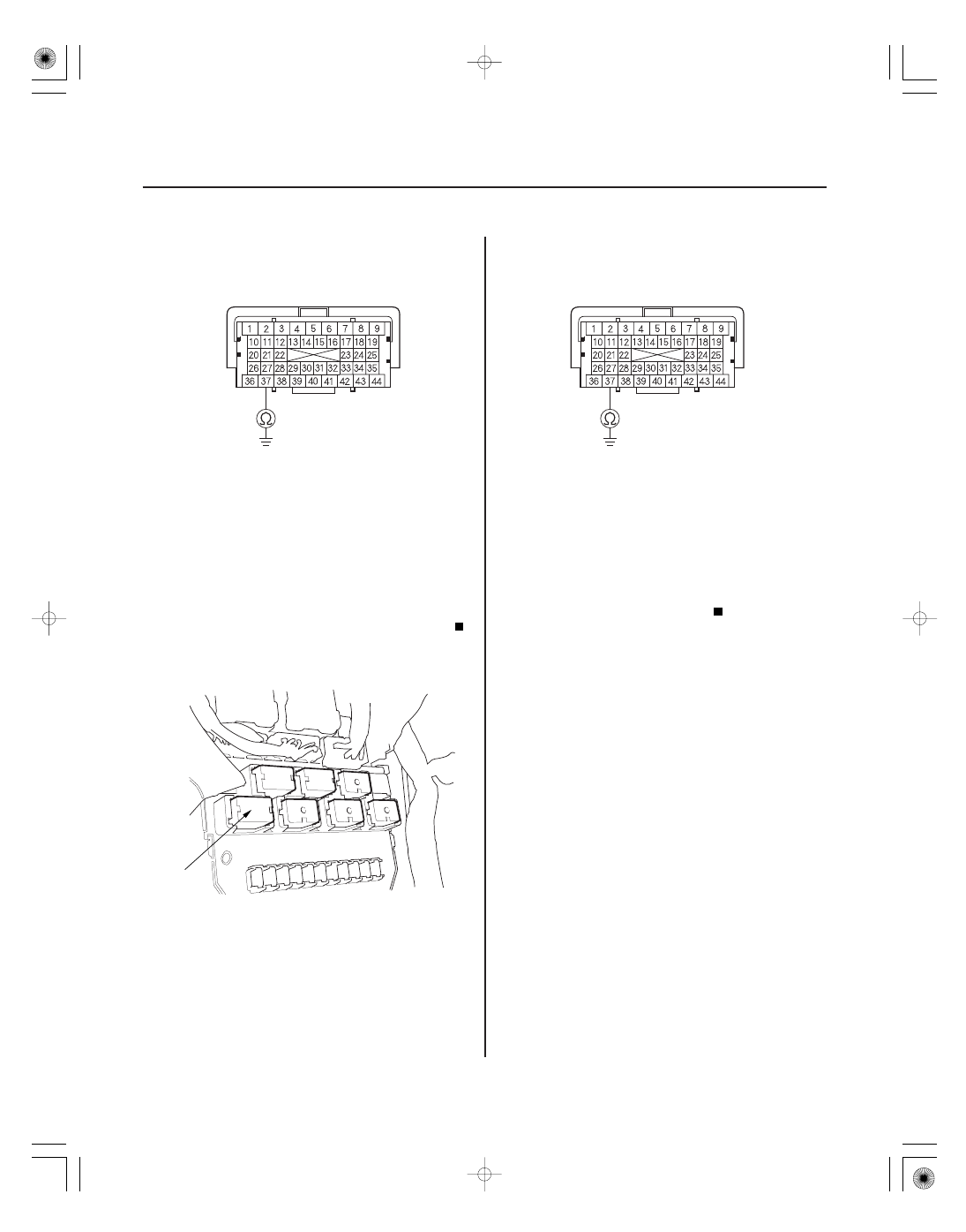
PCM CONNECTOR B (44P)
IG1 (BLK/YEL)
A
PCM CONNECTOR B (44P)
IG1 (BLK/YEL)
35. Check for continuity between PCM connector
terminal B37 and body ground.
Go to step 36.
Replace the No. 19 IG FUEL PUMP (15 A) fuse,
and update the PCM if it does not have the latest
software (see page 11-7), or substitute a known-
good PCM (see page 11-8), then recheck. If the
symptom/indication goes away with a known-good
PCM, replace the original PCM (see page 11-205).
36. Remove PGM-FI main relay 2 (FUEL PUMP) (A)
from the driver’s under-dash fuse/relay box.
37. Check for continuity between PCM connector
terminal B37 and body ground.
Repair short in the wire between the No. 19
IG FUEL PUMP (15 A) fuse and the PCM (B37),
between the No. 19 IG FUEL PUMP (15 A) fuse and
PGM-FI main relay 2 (FUEL PUMP), or between the
No. 19 IG FUEL PUMP (15 A) fuse and the
immobilizer control unit-receiver. Also replace the
No. 19 IG FUEL PUMP (15 A) fuse.
Go to step 38.
38. Remove the rear seat (see page 20-117).
39. Remove the access panel from the floor.
40. Disconnect the fuel pump 5P connector.
Terminal side of female terminals
Terminal side of female terminals
Is ther e continuity?
Is ther e continuity?