Honda Ridgeline. Manual - part 104
01
SJC8A00K771000U0114FAAT00
−
−
−
−
−
−
−
−
DTC U0114:
YES
NO
YES
NO
YES
NO
YES
NO
11-180
PGM-FI System
DTC Troubleshooting (cont’d)
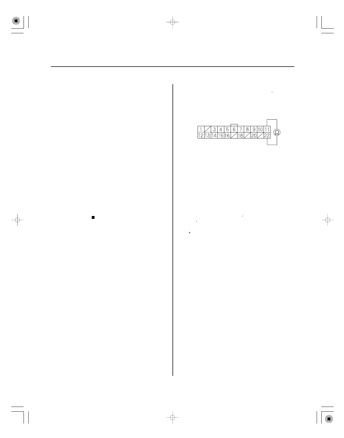
VTM-4 CONTROL UNIT 22P CONNECTOR
CANH
(WHT)
CANL*
(RED)
F-CAN Malfunction (VTM-4
Control Unit-PCM)
NOTE:
• Before you troubleshoot, record all freeze data and
any on-board snapshot, and review the general
troubleshooting information (see page 11-3).
• If DTC U0073 is stored at the same time as DTC
U0114, troubleshoot DTC U0073 first, then recheck
for DTC U0114.
1. Turn the ignition switch ON (II).
2. Clear the DTC with the HDS.
3. Check for Temporary DTCs or DTCs in the DTCs
MENU with the HDS.
Go to step 4.
Intermittent failure, the system is OK at this
time. Check for poor connections or loose terminals
at the gauge control module, the VTM-4 control unit,
and the PCM.
4. Check for DTCs in the DTCs MENU with the HDS.
Go to step 5.
Go to step 8.
5. Turn the ignition switch OFF.
6. Disconnect the VTM-4 control unit 22P connector.
7. Check for continuity between VTM-4 control unit
22P connector terminals No. 11 and No. 22 .
Substitute a known-good VTM-4 control unit,
then go to step 15 and recheck. If no DTCs are
indicated, replace the original VTM-4 control unit,
then go to step 15.
Repair open in the wire between the VTM-4
control unit (No. 11 (No. 22) ) and the PCM (A36
(A1) ), then go to step 15.
: CANL line
8. Check for poor connections at the VTM-4 control
unit 22P connector and 12P connector.
Go to step 9.
Repair the connections, then go to step 15.
Wire side of female terminals
Is DT C U0114 indicated?
Is T CS DT C 41 indicated?
Is ther e continuity?
Ar e the connections OK ?