Honda Ridgeline. Manual - part 69
36
Intake Manifold Tuning (IMT) Valve System
11-40
Fuel and Emissions Systems
System Description (cont’d)
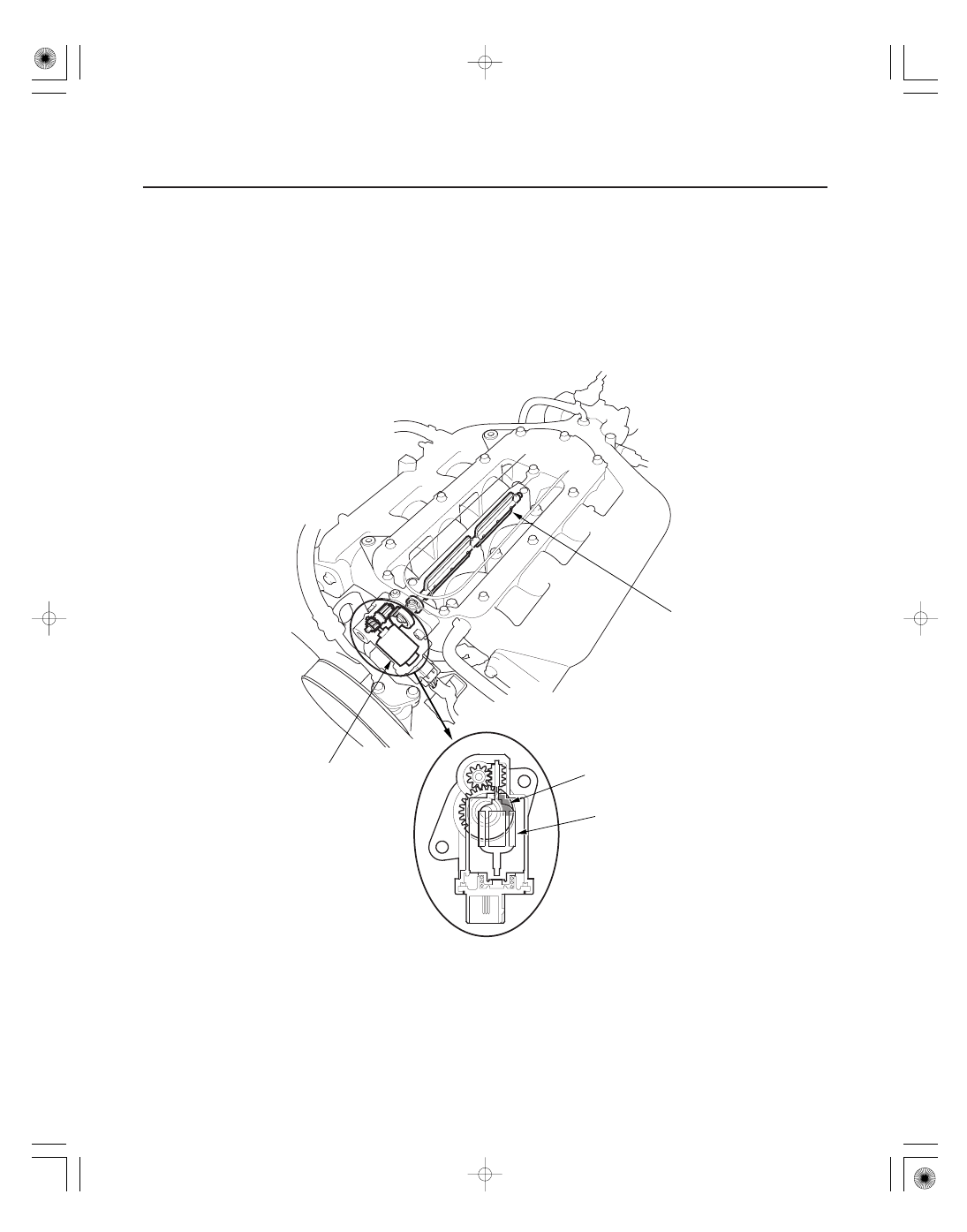
IMT VALVE
IMT ACTUATOR
MAGNET
MOTOR
Engine power is adjusted by opening and closing the intake manifold tuning (IMT) actuator. When the valve is closed,
there is high torque at low engine speed. When the valve is open, there is high torque at high engine speed.
The intake manifold tuning (IMT) valve actuator contains a sensor that detects the IMT valve position and sends it to
the PCM.