Honda Ridgeline. Manual - part 68


  Index      Honda     Honda Ridgeline - service repair manual 2006-2008 year


Search            


Content   ..  66  67  68  69   ..


Honda Ridgeline. Manual - part 68


07

08

Idle Control System

Fuel Supply System

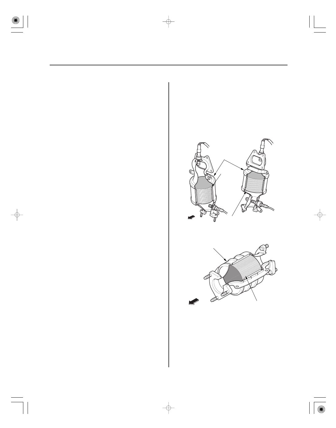
Catalytic Converter System

Brake Pedal Position Switch

Power Steering Pressure (PSP) Switch

Fuel Cutoff Control

Fuel Pump Control

PGM-FI Main Relay 1 and 2

Warm Up/Three Way Catalytic Converter (WU-TWC)
and Under-Floor Three Way Catalytic Converter (TWC)

WU-TWC

TWC

11-36

Fuel and Emissions Systems

System Description (cont’d)

HOUSING

WARM UP
THREE WAY
CATALYST
FRONT
(Bank 2)

WARM UP THREE WAY
CATALYST REAR
(Bank 1)

FRONT OF
VEHICLE

FRONT OF
VEHICLE

UNDER-FLOOR
THREE WAY
CATALYST

HOUSING

When the engine is cold, the A/C compressor is on, the
transmission is in gear, the brake pedal is pressed, the
power steering load is high, or the alternator is
charging, the PCM sends signals to the throttle actuator
to maintain the correct idle speed.

The brake pedal position switch signals the PCM when
the brake pedal is pressed.

The PSP switch signals the PCM when the power
steering load is high.

During deceleration with the throttle valve closed,
current to the injectors is cut off to improve fuel
economy at engine speeds over 950 rpm. Fuel cutoff
control also occurs when the engine speed exceeds
6,500 rpm, regardless of the position of the throttle
valve, to protect the engine from over-revving. When
the vehicle is stopped, the PCM cuts the fuel at engine
speeds over 5,000 rpm. Engine speed of fuel cut is
lower on a cold engine.

When the ignition is turned on, the PCM grounds
PGM-FI main relay 2 (FUEL PUMP) which feeds current
to the fuel pump for 2 seconds to pressurize the fuel
system. With the engine running, the PCM grounds
PGM-FI main relay 2 (FUEL PUMP) and feeds current to
the fuel pump. When the engine is not running and the
ignition is on, the PCM cuts ground to PGM-FI main
relay 2 (FUEL PUMP) which cuts current to the fuel
pump.

PGM-FI main relay 1 (FI MAIN) is energized whenever
the ignition switch is ON (II) to supply battery voltage to
the PCM, power to the injectors, and power for PGM-FI
main relay 2 (FUEL PUMP). PGM-FI main relay 2 (FUEL
PUMP) is energized to supply power to the fuel pump
for 2 seconds when the ignition switch is turned ON (II),
and when the engine is cranking or running.

The WU-TWC/TWC converts hydrocarbons (HC), carbon
monoxide (CO), and oxides of nitrogen (NOx) in the
exhaust gas to carbon dioxide (CO ), nitrogen (N ), and
water vapor.

2

2

30

31

32

Exhaust Gas Recirculation (EGR) System

Positive Crankcase Ventilation (PCV) System

Evaporative Emission (EVAP) Control
System

EGR Valve

EVAP Canister

EVAP Canister Purge Valve

Fuel Tank Pressure (FTP) Sensor

EVAP Canister Vent Shut Valve

11-37

PCV VALVE

BREATHER PIPE

INTAKE MANIFOLD

PCV VALVE

: BLOW-BY VAPOR

: FRESH AIR

O-RING

TERMINAL

SENSOR UNIT

O-RING

O-RING

VALVE

TERMINAL

Refer to the system diagram to see a functional layout
of the system.

The EGR valve lowers peak combustion temperatures
and reduces oxides of nitrogen emissions (NOx) by
recirculating exhaust gas through the intake manifold
and into the combustion chambers.

The PCV valve prevents blow-by gasses from escaping
into the atmosphere by venting them into the intake
manifold.

Refer to the system diagram to see a functional layout
of the system.

The EVAP canister temporarily stores fuel vapor from
the fuel tank until it can be purged from the EVAP
canister into the engine and burned.

When the engine coolant temperature is below 140 °F
(60 °C), the PCM turns off the EVAP canister purge valve
which cuts vacuum to the EVAP canister.

The FTP sensor converts fuel tank absolute pressure
into an electrical input to the PCM.

The EVAP canister vent shut valve is on the EVAP
canister.
The EVAP canister vent shut valve controls the venting
of the EVAP canister.

(cont’d)

09

10

Fuel Cap Warning Message

To make the message go off (with the HDS)

To make the message go off (without the
HDS) (’06 model)

To make the message go off (without the
HDS) (’07-08 models)

First drive cycle

’06 model

’07-08 models

Procedure

Procedure

Procedure

11-38

Fuel and Emissions Systems

System Description (cont’d)

A

Shows ’’CHECK FUEL CAP’’ in the

information display and stores

Temporary DTC

A

Shows ’’TIGHTEN FUEL CAP’’ in the

information display and stores

Temporary DTC

outside temperature display. If the PCM detects a small
volume leak, the MIL may come on during the third
drive cycle, and store a DTC.

During the first drive cycle after a cold start, the PCM
alerts the driver to check the fuel fill cap by showing a
‘‘CHECK FUEL CAP’’ (’06 model) or a ‘‘TIGHTEN FUEL
CAP’’ (’07-08 models) message on the multi-
information display (A), and it stores Temporary DTC
P0457 ‘‘Evaporative Emission (EVAP) System Leak
Detected/Fuel Fill Cap Loose or Missing.’’ Tightening
the fuel cap does not make the message go off
immediately.

1. Tighten the fuel fill cap until it clicks.

2. Clear the Temporary DTC with the HDS.

3. Verify there is no leak by doing the EVAP

FUNCTION TEST in the INSPECTION MENU with
the HDS.

1. Tighten the fuel fill cap until it clicks.

2. The message should go off after several days

normal driving.

1. Tighten the fuel fill cap until it clicks.

2. Turn the ignition switch ON (II), then turn the

ignition switch OFF.

3.

Do step 2 two more times.

The PCM detects a loose or missing fuel fill cap

by showing the information in the odometer/

under certain conditions, and alerts the driver

35

Electronic Throttle Control System Diagram

11-39

GRN
ORN

BLK

WHT
YEL
RED

BLK

YEL/GRN

BLU

GRN

BLU

RED/BLK

RED/BLU

GRN

THROTTLE
BODY

THROTTLE
ACTUATOR

TP SENSOR A

TP SENSOR B

APP
SENSOR A

APP
SENSOR B

From
ETCS CONTROL
RELAY

PCM

VARIOUS
SENSORS

The electronic throttle control system consists of the throttle actuator, throttle position (TP) sensor A/B, accelerator
pedal position (APP) sensor A/B, the electronic throttle control system (ETCS) control relay, and the PCM.

(cont’d)


Content   ..  66  67  68  69   ..