Honda Odyssey 2004. Manual - part 553
−
−
−
−
−
−
*05
13
*06
15
YES
NO
YES
NO
23-154
SRS
DTC Troubleshooting (cont’d)
A
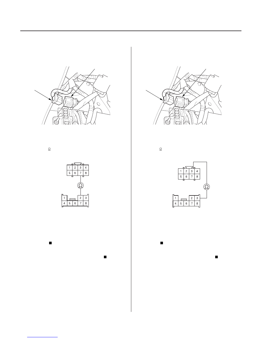
C503
SRS UNIT CONNECTOR C (8P)
YEL/BLU
YEL/BLU
SRS MAIN HARNESS
8P CONNECTOR
A
C503
SRS UNIT CONNECTOR C (8P)
BLU
BLU
SRS MAIN HARNESS
8P CONNECTOR
19. Disconnect the SRS main harness 8P connector (A)
from the dashboard wire harness 8P connector
C503.
20. Check resistance between the No. 7 terminal of
SRS unit connector C (8P) and the No. 2 terminal of
the SRS main harness 8P connector. There should
be 0
1
.
Open in the right side wire harness or
dashboard wire harness; replace the faulty
harness.
Open in the SRS main harness or SRS floor
harness; replace the SRS floor harness.
21. Disconnect the SRS main harness 8P connector (A)
from the dashboard wire harness 8P connector
C503.
22. Check resistance between the No. 3 terminal of
SRS unit connector C (8P) and the No. 3 terminal of
the SRS main harness 8P connector. There should
be 0
1
.
Open in the right side wire harness or
dashboard wire harness; replace the faulty
harness.
Open in the SRS main harness or SRS floor
harness; replace the SRS floor harness.
Wire side of female terminals
Wire side of female terminals
Is the r esistance as specif ied?
Is the r esistance as specif ied?
03/07/29 10:36:04 61S0X050_230_0154