Honda Odyssey 2004. Manual - part 552
−
−
−
−
−
01
*01
S0X4AZ3K79100081094FAAT00
’02 Model
DTC 9-4:
YES
NO
YES
NO
23-150
SRS
DTC Troubleshooting (cont’d)
A
B
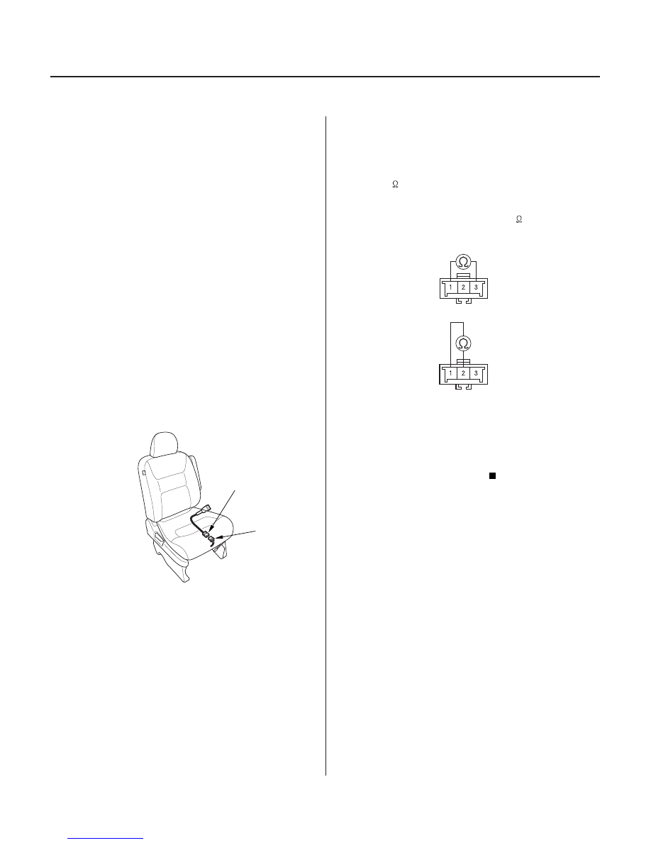
FRONT PASSENGER’S SEAT BELT
BUCKLE SWITCH 3P CONNECTOR
BLK
BLU/RED
BLK
RED/BLU
Faulty Front Passenger’s Seat Belt
Buckle Switch
1. Erase the DTC memory (see page 23-38).
2. Turn the ignition switch ON (II), then buckle and
unbuckle the front passenger’s seat belt several
times.
3. Read the DTC (see page 23-35).
Go to step 4.
Intermittent failure, system is OK at this time.
Go to Troubleshooting Intermittent Failures (see
page 23-39).
4. Turn the ignition switch OFF.
5. Disconnect the front passenger’s seat belt buckle
switch 3P connector (A) from the floor wire harness
3P connector (B).
6. Buckle the front passenger’s seat belt.
• Check resistance between the No. 1 and No. 3
terminals of the front passenger’s seat belt
buckle switch 3P connector. There should be
0
1
.
• Check resistance between the No. 1 and No. 2
terminals of the same connector. There should
be an open circuit, or at least 1 M
.
Go to step 7.
Replace the front passenger’s seat belt buckle
assembly, and clear the DTC.
Terminal side of male terminals
Terminal side of male terminals
Is DT C 9-4 indicated?
Is the r esistance as specif ied?
03/07/29 10:34:58 61S0X050_230_0150