Honda Odyssey 2004. Manual - part 456
01
S0X4A00J32300063101KBAT01
01
S0X4A00J32300016511KBAT02
VANITY MIRROR LIGHT BULB: 1.1 W
CENTER POCKET LIGHT BULB: 3.4 W
22-152
22-152
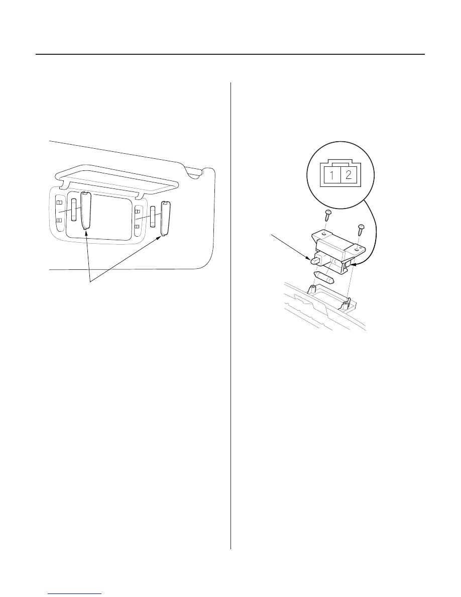
Interior Lights
Vanity Mirror Light Replacement
Center Pocket Light Replacement
A
A
1. Open the sunvisor.
2. Carefully pry off the lens (A) with a small
screwdriver.
1. Remove the center pocket (see page 20-67).
2. Disconnect the 2P connector from the center pocket
light.
3. Check for continuity between the No. 1 and No. 2
terminals.
• With the button (A) pressed, there should be no
continuity.
• With the button (A) released, there should be
continuity.
4. If the continuity is not as specified, check the bulb,
if the bulb is OK, replace the light.
03/07/29 10:22:29 61S0X050_220_0154