Honda Odyssey 2004. Manual - part 454


  Index      Honda     Honda Odyssey 2004 - service repair manual 2004 year


Search            


Content   ..  452  453  454  455   ..


Honda Odyssey 2004. Manual - part 454


03

Door Multiplex Control Unit

Cavity

Wire

Test condition

Test: Desired result

Possible cause if result is not obtained

22-144

Entry Lights Control System

Control Unit Input Test (cont’d)

BLK/RED

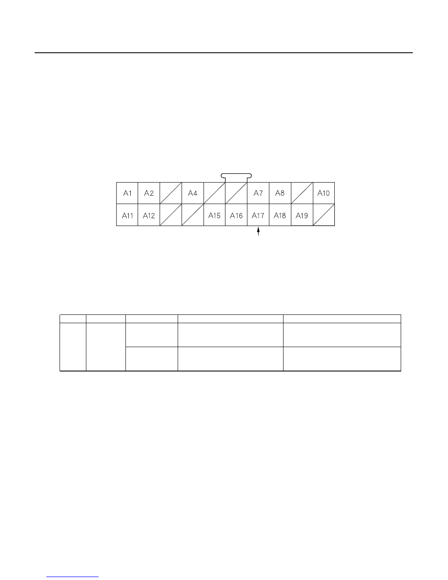
DOOR MULTIPLEX CONTROL UNIT CONNECTOR A

10. Remove the driver’s door panel and disconnect the 20P connector A from the door multiplex control unit.

11. Inspect all connector and socket terminals to be sure they are making good contact.

• If the terminals are bent, loose or corroded, repair them as necessary, and recheck the system.
• If the terminals look OK, go to step 12.

12. Reconnect the connectors to the door unit, and make the input test at the connector.

• If a test indicates a problem, find and correct the cause, then recheck the system.
• If the input test proves OK, go to step 13.


A17

BLK/RED

Driver’s door
lock knob
locked

Check for voltage to ground:
There should be 5 V or more.

Faulty driver’s door lock actuator
Poor ground (G401)
An open in the wire

Driver’s door
lock knob
unlocked

Check for voltage to ground:
There should be 1 V or less.

Faulty driver’s door lock actuator
Short to ground

13. If all the input tests prove OK, one of the control units must be faulty. Substitute a known-good control unit for the

one that is most likely at fault, then recheck the system. If the system works properly, the original control unit is
faulty; replace it. If there is still a malfunction, substitute a known-good control unit for the next unit most likely to
be at fault, and recheck. If the system works properly, the original unit is faulty; replace it.

Wire side of female terminals

03/07/29 10:21:32 61S0X050_220_0146

01

S0X4A00J32323334311FEAT01

01

S0X4A00J32323334301FEAT02

22-145

22-145

Ignition Key Switch Test

Ignition Key Light Test

A

A

NOTE: For more key-in beeper information, refer to the
circuit diagram (see page 22-109) and input test (see
page 22-110).

When the ignition key is not removed, the key-in beeper
in the driver’s multiplex control unit senses ground
through the closed ignition key switch. When you open
the driver’s door, the beeper circuit senses ground
through the closed door switch.

1. Remove the steering column upper and lower

covers (see page 17-25).

2. Disconnect the 7P connector.

NOTE: Lock tab (A) points down when installed.

3. Check for continuity between terminals No. 1 and

No. 3.

• There should be continuity with the key in the

ignition switch.

• There should be no continuity with the key

removed.

4. If the continuity is not as specified, replace the

ignition key switch.

1. Remove the steering column upper and lower

covers (see page 17-25).

2. Disconnect the 7P connector.

NOTE: Lock tab (A) points down when installed.

3. The LED should come on when power is connected

to terminal No. 7 and ground is connected to
terminal No. 6.

4. If the LED does not come on, replace the ignition

key switch.

03/07/29 10:21:33 61S0X050_220_0147

*01

S0X4A00J32300000000DAAT00

22-146

Interior Lights

Component Location Index

PASSENGER’S
VANITY MIRROR
LIGHTS

RIGHT REAR INDIVIDUAL
MAP LIGHTS

DRIVER’S VANITY
MIRROR LIGHTS

INTERIOR LIGHTS RELAY

LEFT REAR INDIVIDUAL MAP LIGHTS

FRONT INDIVIDUAL
MAP LIGHTS

CARGO AREA LIGHT

INTERIOR LIGHTS SWITCH

CENTER POCKET LIGHT

Replacement, page 22-152

Test, page 22-150

Wire colors: BLK/BLU,
WHT/BLU, LT GRN, BLK

Test, page 22-88

Test, page 22-150

Test, page 22-149

Test, page 22-151

Test, page 22-148

NOTE: Use Interior Lights to troubleshoot LX model ceiling lights. For EX and EXL models, page 22-138.

03/07/29 10:21:35 61S0X050_220_0148

Replacement, page 22-152

Replacement, page 22-152

*01

S0X4A00J32300000000EAAT00

22-147

Circuit Diagram

*3

*4

RED/BLK

WHT/BLU *

RED/BLK *

RED/BLK *

WHT/BLU

*4

*3

: ’03 04 models

: ’99 02 models

RED/BLK

4

3’

1’

1

3

2

1

2

3

1

3

3

1

1

3

1

3

2

2

2

2

ON

G582

G401

BLK

(3.4W)

OPEN

CLOSE

1

2

BLK

RED/BLK

WHT/BLU *

CLOSE

OPEN

OPEN

CLOSE

BLK

BLK

2

RED/BLK

BLK

BLK

1

5

3

G501

BLK

RED

OFF

ON

GRN/WHT

6

4

DOOR

BLK/WHT

DOOR

OFF

LT GRN

G401

BLK

WHT/BLU

BLK/BLU

BLK/BLU

BLK/BLU

OFF

ON

WHT/BLU

FRONT LIGHTS

BLK

WHT/BLU

WHT/BLU

GRN/WHT

BLK/BLU

BLK/BLU

GRN/WHT

WHT/BLU

WHT/BLU

GRN/WHT

BLK/BLU

BLK/BLU

GRN/WHT

WHT/BLU

*2

: LX model

: EX and EXL models

*1

WHT/BLU

No.11
(10A)

G582

YEL

UNDER HOOD FUSE/RELAY BOX

No.54 (40A)

No.41 (120A)

BATTERY

PASSENGER’S
UNDER DASH
FUSE/RELAY BOX

LEFT
REAR
LIGHT
(10W)

LEFT
MIDDLE
LIGHT
(10W)

RIGHT
REAR
LIGHT
(10W)

RIGHT
MIDDLE
LIGHT
(10W)

LEFT
(6.2W)

RIGHT
(6.2W)

CARGO
AREA
LIGHT
(8W)

COMBINATION
LIGHT SWITCH

COMBINATION
LIGHT SWITCH

INTERIOR
LIGHTS
RELAY

INTERIOR
LIGHTS
SWITCH

LIGHT
(0.84W)

DRIVER’S
MULTIPLEX
CONTROL UNIT

CENTER
POCKET
LIGHT

PASSENGER’S
VANITY MIRROR
LIGHT
(1.1Wx2)

DRIVER’S
VANITY MIRROR
LIGHT
(1.1Wx2)

PASSENGER’S
MULTIPLEX
CONTROL UNIT *
GAUGE
ASSEMBLY *

4

3

3

4

1

2

03/07/29 10:21:36 61S0X050_220_0149


Content   ..  452  453  454  455   ..