Honda Odyssey 2004. Manual - part 313
+
+
+
+
+
−
+
−
+
+
+
+
+
−
−
+
−
−
+
−
−
01
02
S0X4A07K70100081110FAAT00
+
+
+
+
+
+
+
+
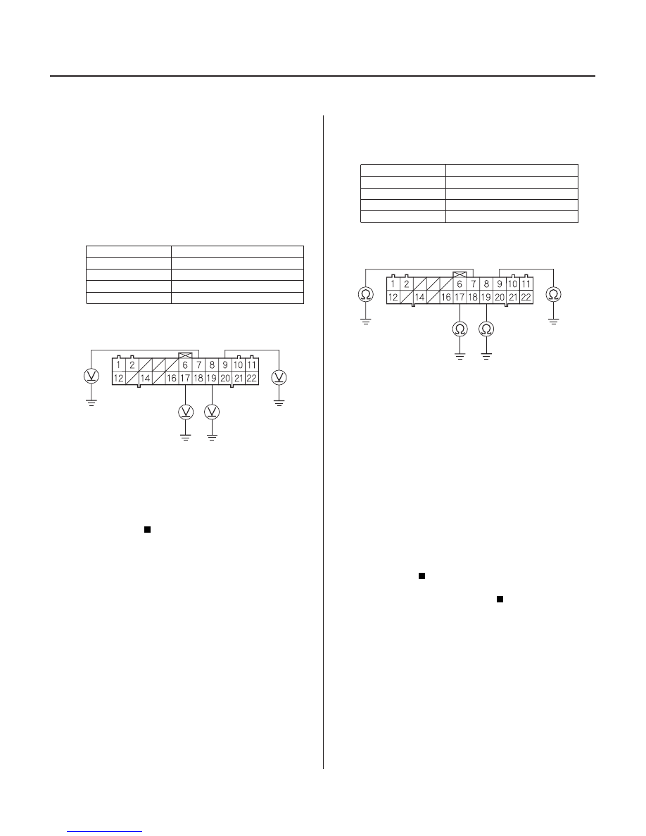
DTC 11, 13, 15, 17:
DTC
Appropriate Terminal
YES
NO
DTC
Appropriate Terminal
YES
NO
YES
NO
19-58
ABS Components
DTC Troubleshooting
ABS CONTROL UNIT CONNECTOR A (22P)
FLW (
) (GRN/BLU)
FRW (
) (GRN/BLK)
RLW (
) (LT BLU)
RRW (
)
(GRN/YEL)
ABS CONTROL UNIT CONNECTOR A (22P)
FLW (
) (GRN/BLU)
FRW (
) (GRN/BLK)
RLW (
) (LT BLU)
RRW (
)
(GRN/YEL)
Wheel Sensor (Open/
Short to Body Ground/Short to Power)
1. Disconnect the ABS control unit connector A (22P).
2. Start the engine.
3. Measure the voltage between the appropriate
wheel sensor (
) circuit terminal and body ground
(see table).
11 (Right-front)
No. 9: FRW (
)
13 (Left-front)
No. 7: FLW (
)
15 (Right-rear)
No. 19: RRW (
)
17 (Left-rear)
No. 17: RLW (
)
Repair short to power in the (
) circuit wire
between the ABS control unit and the appropriate
wheel sensor.
Go to step 4.
4. Check for continuity between the appropriate
wheel sensor (
) circuit terminal and body ground
(see table).
11 (Right-front)
No. 9: FRW (
)
13 (Left-front)
No. 7: FLW (
)
15 (Right-rear)
No. 19: RRW (
)
17 (Left-rear)
No. 17: RLW (
)
Go to step 5.
Go to step 6.
5. Disconnect the harness 2P connector from the
appropriate wheel sensor, then check for continuity
between the (
) and (
) terminals of the harness
and body ground.
Repair short to body ground in the (
) or (
)
circuit wire between the ABS control unit and the
wheel sensor.
Replace the wheel sensor.
Wire side of female terminals
Wire side of female terminals
Is ther e 2 V or mor e?
Is ther e continuity?
Is ther e continuity?
03/07/29 09:55:46 61S0X050_190_0058