Honda Odyssey 2004. Manual - part 312
16
17
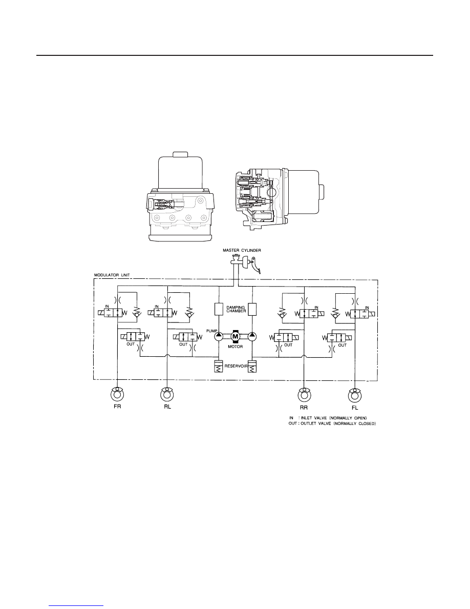
ABS Modulator
19-54
ABS Components
System Description (cont’d)
SOLENOID VALVE
PUMP MOTOR
The ABS modulator consists of the inlet solenoid valve, outlet solenoid valve, reservoir, pump, pump motor, and the
damping chamber. The modulator reduces the caliper fluid pressure directly. It is a circulating-type modulator
because the brake fluid circulates through the caliper, reservoir, and the master cylinder. The hydraulic control has
three modes: pressure intensifying, pressure retaining, and pressure reducing. The hydraulic circuit is an independent
four channel-type, one channel for each wheel.
Pressure intensifying mode:
Inlet valve open, outlet valve closed
Master cylinder fluid is pumped out to the caliper.
Pressure retaining mode:
Inlet valve closed, outlet valve closed
Caliper fluid is retained by the inlet valve and outlet valve.
Pressure reducing mode:
Inlet valve closed, outlet valve open
Caliper fluid flows through the outlet valve to the reservoir.
Motor operation mode:
When starting the pressure reducing mode, the pump motor is ON.
When stopping ABS operation, the pump motor is OFF.
The caliper fluid is pumped out by the pump, through the damping chamber, to the
master cylinder.
03/07/29 09:55:42 61S0X050_190_0054