Honda Odyssey 2004. Manual - part 301


  Index      Honda     Honda Odyssey 2004 - service repair manual 2004 year


Search            


Content   ..  299  300  301  302   ..


Honda Odyssey 2004. Manual - part 301


*01

S0X4A00D14300014832EAAT00

19-10

Conventional Brake Components

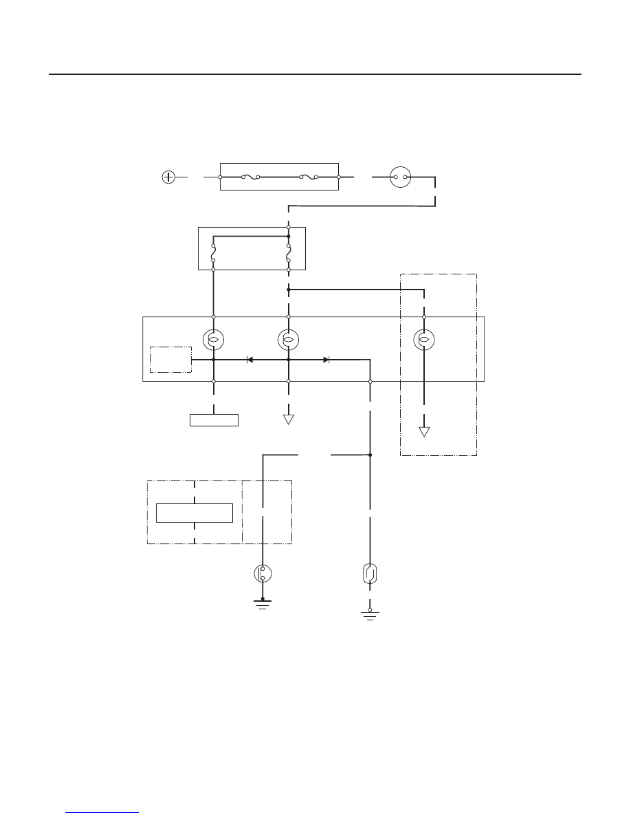
Brake System Indicator Circuit Diagram

PARKING BRAKE SWITCH
CLOSED: Pedal pressed
OPEN: Pedal released

BRAKE FLUID
LEVEL SWITCH
CLOSED: Float down
OPEN: Float up

BRAKE
SYSTEM
INDICATOR

UNDER-DASH DRIVER’S
FUSE/RELAY BOX

IGNITION
SWITCH

UNDER-HOOD FUSE/RELAY BOX

GAUGE
ASSEMBLY

IG1 MAIN (50A)

G301

Canada

USA

BATTERY

BATTERY (120A)

•ABS/TCS CONTROL UNIT

DRL
INDICATOR
LIGHT

Canada

DAYTIME RUNNING
LIGHTS CONTROL UNIT

YEL

YEL

YEL

GRN/RED

•ABS CONTROL UNIT

FUSE 6
(15A)

FUSE 9
(10A)

B11

C14

B14

BLK

WHT

BLK/YEL

BLK/YEL

CHARGING
SYSTEM
INDICATOR

BLU/WHT

YEL/WHT

GRN/RED

B8

WHT/BLU

ALTERNATOR

GRN/RED

GRN/RED

BLK

SAFETY
INDICATOR
CIRCUIT

DAYTIME RUNNING
LIGHTS CONTROL UNIT

GRN/WHT

GRN/RED

IG1

03/07/29 09:53:51 61S0X050_190_0010

01

S0X4A00D00060845131FEAT00

*01

S0X4A00D14300014741FEAT00

19-11

19-11

Parking Brake Switch Test

Brake Fluid Level Switch Test

A

C

B

A

B

D

C

1. Disconnect the parking brake switch connector (A)

from the switch (B).

2. Check for continuity between the positive terminal

(C) and body ground.

• With the parking brake pedal pressed, there

should be continuity.

• With the parking brake pedal released, there

should be no continuity.

NOTE:

• If both the ABS or TCS indicator and the brake

system indicator come on at the same time,
check the ABS (see page 19-41) or TCS (see page
19-81) first.

• If the parking brake switch/fluid level switch is

OK, but the brake system indicator does not
function, check the ABS or TCS (For Canada
model: do the input test for the daytime running
lights control unit first.

1. Remove the reservoir cap (A). Check that the float

(B) moves up and down freely; if it does not,
replace the reservoir cap assembly.

2. Check for continuity between the terminals with the

float in the down position (C) and the up position
(D):

• With the float up, there should be no continuity.
• With the float down, there should be continuity.

03/07/29 09:53:52 61S0X050_190_0011

11

12

*01

S0X4A00D14300014791MDAT10

Brake Pad Thickness:

Standard:

10.5

11.5 mm (0.41

0.45 in.)

Service Limit: 1.6 mm (0.06 in.)

19-12

Conventional Brake Components

Front Brake Pad Inspection and Replacement

A
9.8 N·m
(1.0 kgf·m, 7.2 lbf·ft)

B

C

A

C

C

A

B

A

’99 Model:

’00-04 Models:

A

Frequent inhalation of brake pad dust, regardless of
material composition, could be hazardous to your
health.

• Avoid breathing dust particles.
• Never use an air hose or brush to clean brake

assemblies. Use an OSHA-approved vacuum
cleaner.

1. Loosen the front wheel nuts slightly. Raise the front

of the vehicle, and support it with safety stands in
the proper locations (see page 1-15). Remove the
front wheels.

2. Remove the brake hose mounting bolt (A) from the

knuckle.

3. Hold the caliper pin with a wrench, being careful

not to damage the pin boot. Remove the caliper
bolt (B) with another wrench.

4. Pivot the caliper (C) up out of the way. Check the

brake hose and pin boots for damage and
deterioration.

5. Remove the pad shims (A), pad retainers (B), and

brake pads (C). ’99-01 models have two pairs of the
pad shim. ’02-04 models have one pair of the pad
shim.

6. Using vernier calipers, measure the thickness of

each brake pad lining. The measurement does not
include pad backing plate (A) thickness.

7. If the brake pad thickness is less than the service

limit, replace the front pads as a set.

8. Clean the caliper thoroughly; remove any rust, and

check for grooves and cracks.

03/07/29 09:53:53 61S0X050_190_0012

14

15

*02

19-13

A

A

B

C

B

A

B
8 x 1.0 mm
26 N·m
(2.7 kgf·m, 20 lbf·ft)

A

9. Check the brake disc for damage and cracks.

10. Install the pad retainers (A).

11. Apply Molykote M77 grease or Daikalub 528D

grease to both sides of the pad shims (A) and the
back of the brake pads (B). Wipe excess grease off
the shim. Contaminated brake discs and pads
reduce stopping ability. Keep grease off the discs
and brake pads.

12. Install the brake pads and pad shims correctly.

’99-01 models have two pairs of the pad shim.
’02-04 models have one pair of the pad shim. Install
the brake pad with the wear indicator (C) on the
inside.

13. Push in the piston (A) so that the caliper will fit over

the pads. Make sure that the piston boot is in
position to prevent damaging it when pivoting the
caliper down.

NOTE: Check the brake fluid level, the brake fluid
may overflow the reservoir if too full.

14. Pivot the caliper down into position. Hold the

caliper pin with a wrench, being careful not to
damage the pin boot. Install the caliper bolt (B),
with another wrench, and tigthen it to proper
specification.

15. Install the brake hose onto the knuckle.

16. Press the brake pedal several times to make sure

the brakes work, then test-drive the vehicle.

NOTE: Engagement of the brake may require a
greater pedal stroke immediately after the brake
pads have been replaced as a set. Several
applications of the brake pedal will restore the
normal pedal stroke.

17. After installation, check for leaks at hose and line

joints or connections, and retighten if necessary.

03/07/29 09:53:53 61S0X050_190_0013


Content   ..  299  300  301  302   ..