Honda Element. Manual - part 798


  Index      Honda     Honda Element - service repair manual 2007-2008 year


Search            


Content   ..  796  797  798  799   ..


Honda Element. Manual - part 798


5. Short the SCS line with the HDS.  

6. Disconnect ECM/PCM connector E (31P).  

7. Disconnect the gauge control module 36P connector.  

8. Disconnect the VSA modulator-control unit 47P connector.  

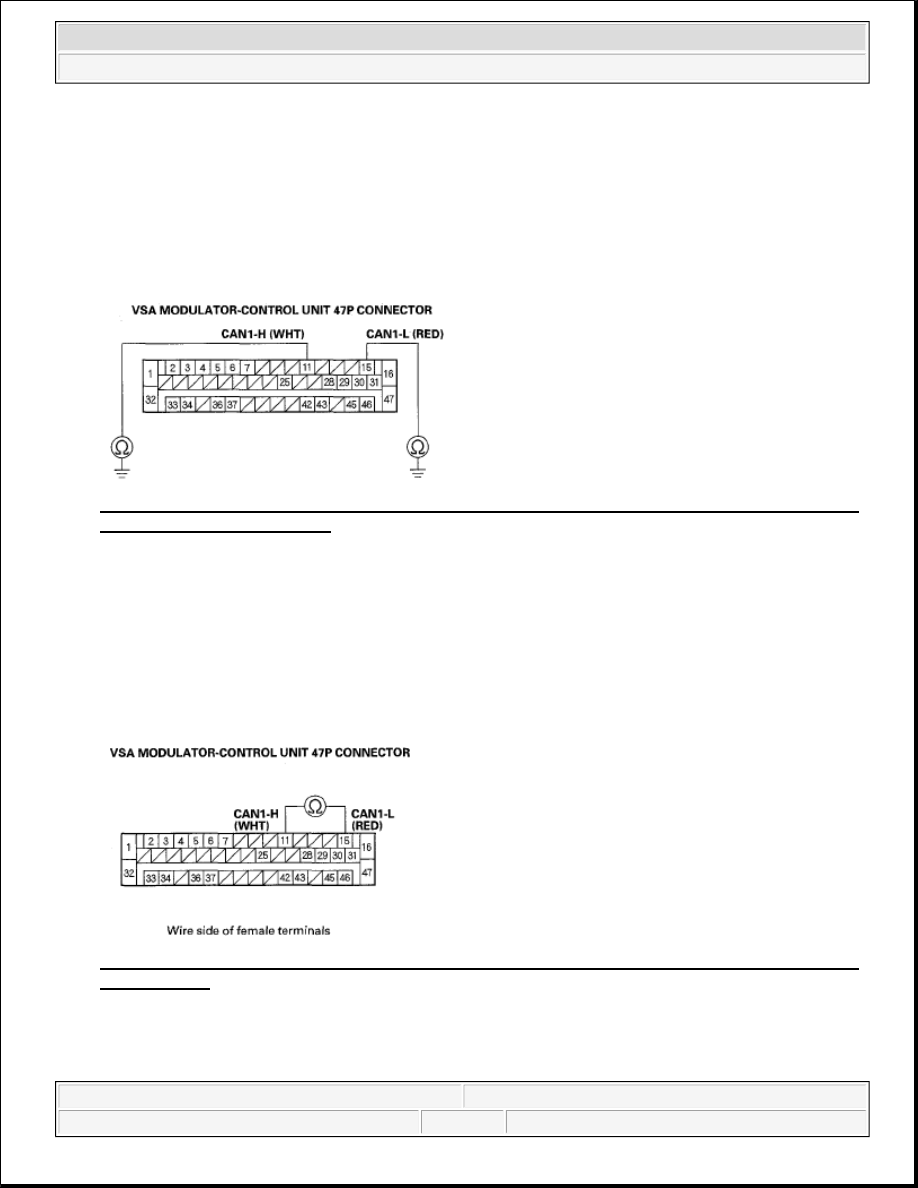
9. Check for continuity between the VSA modulator-control unit 47P connector terminals No. 11, and No. 

15 and body ground individually. 

Fig. 50: Checking Continuity Between VSA Modulator-Control Unit 47P Connector Terminals No. 
11, And 15 And Body Ground
 
Courtesy of AMERICAN HONDA MOTOR CO., INC. 

Is there continuity?  

YES -Repair the short to body ground on the appropriate wire. 

NO -Go to step 10. 

10. Check for continuity between VSA modulator-control unit 47P connector terminals No. 11 and No. 15. 

Fig. 51: Checking Continuity Between VSA Modulator-Control Unit 47P Connector Terminals No. 
11 And No. 15
 
Courtesy of AMERICAN HONDA MOTOR CO., INC. 

Is there continuity?  


2007 Honda Element EX 

2007-2008 BRAKES VSA (Vehicle Stability Assist) System Components - Element


YES -Repair short in the wire between VSA modulator-control unit 47P connector terminals No. 11 
(CAN1-H line) and No. 15 (CAN1-L line). 

NO -Go to step 11. 

11. Check for continuity between VSA modulator-control unit 47P connector terminal and gauge control 

module 36P connector terminal (see table). 

CONTINUITY SPECIFICATIONS 

Fig. 52: Checking Continuity Between VSA Modulator-Control Unit 47P Connector Terminal And 
Gauge Control Module 36P Connector Terminal
 
Courtesy of AMERICAN HONDA MOTOR CO., INC. 

Is there continuity?  

YES -Check for loose terminals in the gauge control module 36P connector. If necessary, substitute a 
known-good gauge control module, then go to step 1 and recheck. If it is OK, replace the original gauge 
control module (see REWRITING THE ODO DATA AND TRANSFERRING MAINTENANCE 
MINDER ON A NEW GAUGE CONTROL MODULE
 ). If DTCs are indicated, replace the VSA 
modulator-control unit (see VSA MODULATOR-CONTROL UNIT REMOVAL AND 
INSTALLATION
 ). 

NO -Repair open in the wire between the gauge control module and the VSA modulator-control unit. 

STEERING ANGLE SENSOR REPLACEMENT 

Sign

Connector Terminal No.

VSA Modulator-control Unit Gauge Control Module

CAN1-L

15

28

CAN1-H

11

29

NOTE:

Do not damage or drop the combination switch as the steering angle sensor is 


2007 Honda Element EX 

2007-2008 BRAKES VSA (Vehicle Stability Assist) System Components - Element


1. Remove the steering wheel (see STEERING WHEEL REMOVAL ).  

2. Remove the steering column covers (see STEERING COLUMN REMOVAL AND 

INSTALLATION ) and the cable reel (see CABLE REEL REPLACEMENT ).  

3. Remove the combination switch assembly (see STEERING COLUMN REMOVAL AND 

INSTALLATION ).  

4. Remove the combination light switch (A) and the wiper/washer switch (B). 

Fig. 53: Removing Combination Light Switch And Wiper/Washer Switch 
Courtesy of AMERICAN HONDA MOTOR CO., INC. 

5. Replace the combination switch body (C).  

6. Install the combination switch in the reverse order of removal. 

SENSOR CLUSTER REPLACEMENT 

1. Make sure the ignition switch OFF.  

2. Remove the center console: SC model (see CENTER CONSOLE REMOVAL/INSTALLATION ), 

Except SC model (see LX, EX MODELS ).  

3. Disconnect the sensor cluster 6P connector (A). 

sensitive to shock and vibration.

NOTE:

Do not remove the steering angle sensor from the combination 
switch body.  

When installing the cable reel, set the turn signal canceling sleeve 
position (see INSTALLATION ).  

NOTE:

Do not damage or drop the sensor as it is sensitive. 

Do not use air or electric impact tools.  


2007 Honda Element EX 

2007-2008 BRAKES VSA (Vehicle Stability Assist) System Components - Element


Fig. 54: Disconnecting Sensor Cluster 6P Connector With Torque Specification 
Courtesy of AMERICAN HONDA MOTOR CO., INC. 

4. Remove the sensor cluster (B).  

5. Install the sensor in the reverse order of removal.  

6. Do the VSA sensor neutral position memorization (see VSA SENSOR NEUTRAL POSITION 

MEMORIZATION ).  

VSA SENSOR NEUTRAL POSITION MEMORIZATION 

1. Park the vehicle on a flat and level surface.  

2. With the ignition switch OFF, connect the HDS to the data link connector (DLC) (A) under the driver's 

side of the dashboard. 

NOTE:

Do not press the brake pedal during this procedure.


2007 Honda Element EX 

2007-2008 BRAKES VSA (Vehicle Stability Assist) System Components - Element


Content   ..  796  797  798  799   ..