Honda Element. Manual - part 797


  Index      Honda     Honda Element - service repair manual 2007-2008 year


Search            


Content   ..  795  796  797  798   ..


Honda Element. Manual - part 797


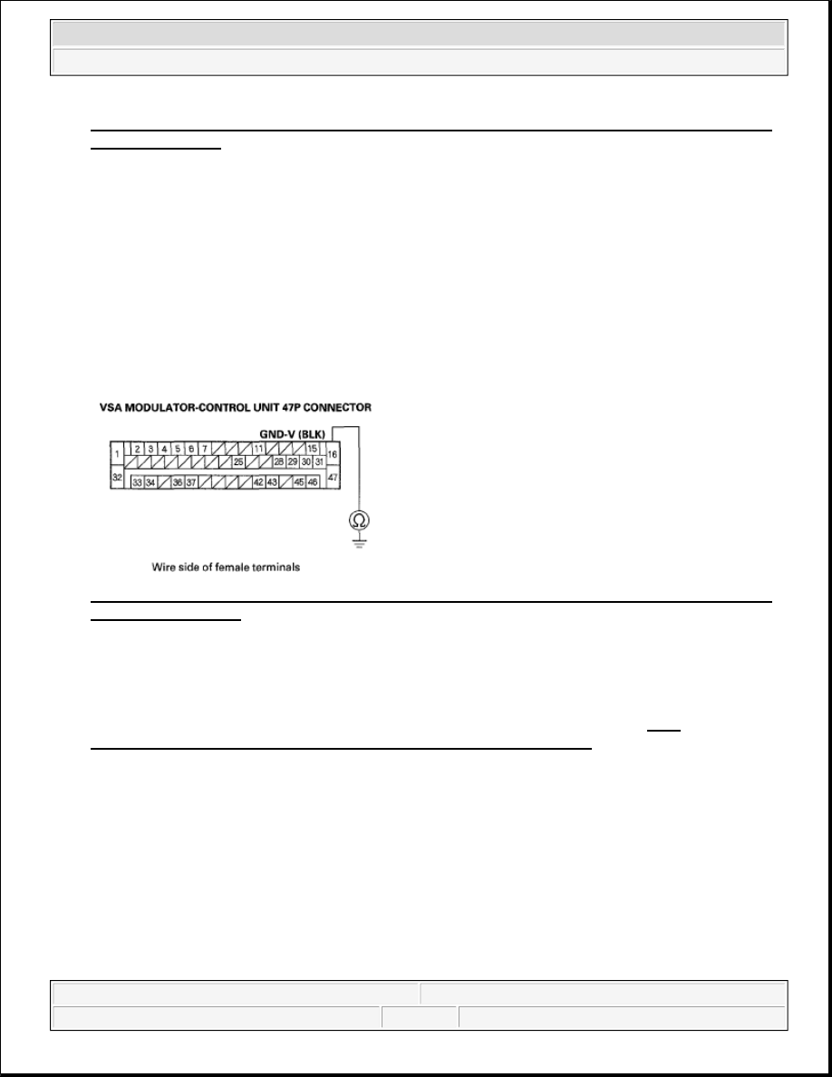
Fig. 46: Measuring Voltage Between VSA Modulator-Control Unit 47P Connector Terminal No. 4 
And Body Ground
 
Courtesy of AMERICAN HONDA MOTOR CO., INC. 

Is there battery voltage?  

YES -Go to step 9. 

NO -Repair open in the wire between the No. 4 (10 A) in the under-dash fuse/relay box and the VSA 
modulator-control unit. 

9. Turn the ignition switch OFF.  

10. Check for continuity between VSA modulator-control unit 47P connector terminal No. 16 and body 

ground. 

Fig. 47: Checking Continuity Between VSA Modulator-Control Unit 47P Connector Terminal No. 
16 And Body Ground
 
Courtesy of AMERICAN HONDA MOTOR CO., INC. 

Is there continuity?  

YES -Check for loose terminals in the VSA modulator-control unit 47P connector, clean terminal G202 
and recheck. If necessary, substitute a known-good VSA modulator-control unit (see VSA 
MODULATOR-CONTROL UNIT REMOVAL AND INSTALLATION
 ), and retest. 

NO -Repair open in the wire between the VSA modulator-control unit and body ground (G202). 

BRAKE SYSTEM INDICATOR DOES NOT GO OFF, AND NO DTCS ARE STORED 

1. Release the parking brake.  

2. Turn the ignition switch ON (II).  

3. Check the brake system indicator when the ignition switch is turned ON (II). 

Does the indicator come on then go off?  

YES -Intermittent failure, the system is OK at this time. Check for loose terminals between the gauge 


2007 Honda Element EX 

2007-2008 BRAKES VSA (Vehicle Stability Assist) System Components - Element


control module 36P connector and the VSA modulator-control unit 47P connector. Refer to intermittent 
failures troubleshooting (see 

INTERMITTENT FAILURES

 ). 

NO -Go to step 4. 

4. Check the BRAKE INDICATOR in the VSA DATA LIST with the HDS. 

Does it indicate OFF?  

YES - 

USA models: Go to step 6.  

Canada models: Go to step 5.  

NO -Check for loose terminals in the VSA modulator-control unit 47P connector. If necessary, substitute 
a known-good VSA modulator-control unit (see VSA MODULATOR-CONTROL UNIT REMOVAL 
AND INSTALLATION
 ), and retest. 

5. Canada models: Do the daytime running lights control unit input test (see DAYTIME RUNNING 

LIGHTS CONTROL UNIT INPUT TEST ). 

Is the test OK?  

YES -Go to step 6. 

NO -Troubleshoot the daytime running lights system. 

6. Turn the ignition switch OFF.  

7. Disconnect the parking brake switch 1P connector.  

8. Turn the ignition switch ON (II). 

Does the brake system indicator go off ?  

YES -Replace the parking brake switch (see PARKING BRAKE CABLE REPLACEMENT ). 

NO -Go to step 9. 

9. Turn the ignition switch OFF.  

10. Disconnect the gauge control module 36P connector.  

11. Check for continuity between parking brake switch 1P connector terminal No. 1 and body ground. 


2007 Honda Element EX 

2007-2008 BRAKES VSA (Vehicle Stability Assist) System Components - Element


Fig. 48: Checking Continuity Between Parking Brake Switch 1P Connector Terminal No. 1 And 
Body Ground
 
Courtesy of AMERICAN HONDA MOTOR CO., INC. 

Is there continuity?  

YES -Repair short to body ground in the wire between the gauge control module and the parking brake 
switch. 

NO -Check for loose terminals in the gauge control module 36P connector. If necessary, substitute a 
known-good gauge control module, then go to step 1 and recheck. If it is OK, replace the original gauge 
control module (see REWRITING THE ODO DATA AND TRANSFERRING MAINTENANCE 
MINDER ON A NEW GAUGE CONTROL MODULE
 ). 

VSA ACTIVATION INDICATOR DOES NOT GO OFF, AND NO DTCS ARE STORED 

1. Turn the ignition switch ON (II).  

2. Check the VSA activation indicator for several seconds when the ignition switch is turned ON (II). 

Does the indicator come on then go off?  

YES -Intermittent failure, the system is OK at this time. 

NO -Go to step 3. 

3. Turn the ignition switch OFF.  

4. Check the VSA OFF switch (see VSA OFF SWITCH TEST ). 

Is the VSA OFF switch OK?  

YES -Go to step 5. 

NO -Replace the VSA OFF switch (see VSA OFF SWITCH TEST ). 

5. Disconnect the gauge control module 36P connector.  

6. Disconnect the VSA OFF switch 10P connector. 


2007 Honda Element EX 

2007-2008 BRAKES VSA (Vehicle Stability Assist) System Components - Element


7. Check for continuity between VSA OFF switch 10P connector terminal No. 2 and body ground. 

Fig. 49: Checking Continuity Between VSA Off Switch 10P Connector Terminal No. 2 And Body 
Ground
 
Courtesy of AMERICAN HONDA MOTOR CO., INC. 

Is there continuity?  

YES -Repair short to body ground in the wire between the gauge control module and the VSA OFF 
switch. 

NO -Substitute a known-good gauge control module, then go to step 1 and recheck. If it is OK, replace 
the original gauge control module (see REWRITING THE ODO DATA AND TRANSFERRING 
MAINTENANCE MINDER ON A NEW GAUGE CONTROL MODULE
 ). 

ABS INDICATOR, BRAKE SYSTEM INDICATOR, AND VSA INDICATOR DO NOT GO OFF AT 
THE SAME TIME 

1. Release the parking brake.  

2. Turn the ignition switch ON (II).  

3. Check the ABS indicator, the brake system indicator, and VSA indicator for several seconds when the 

ignition switch is turned ON (II). 

Do the indicators come on then go off?  

YES -Intermittent failure, the system is OK at this time. Check for loose terminals between the gauge 
control module 36P connector and the VSA modulator-control unit 47P connector. Refer to intermittent 
failures troubleshooting (see 

INTERMITTENT FAILURES

 ). 

NO -Go to step 4. 

4. Turn the ignition switch OFF.  

NOTE:

Check for gauges DTCs with the HDS (see WIRE COLOR CODES ). If gauges 
DTCs are stored, troubleshoot those DTCs first.


2007 Honda Element EX 

2007-2008 BRAKES VSA (Vehicle Stability Assist) System Components - Element


Content   ..  795  796  797  798   ..