Honda Element. Manual - part 188


  Index      Honda     Honda Element - service repair manual 2007-2008 year


Search            


Content   ..  186  187  188  189   ..


Honda Element. Manual - part 188


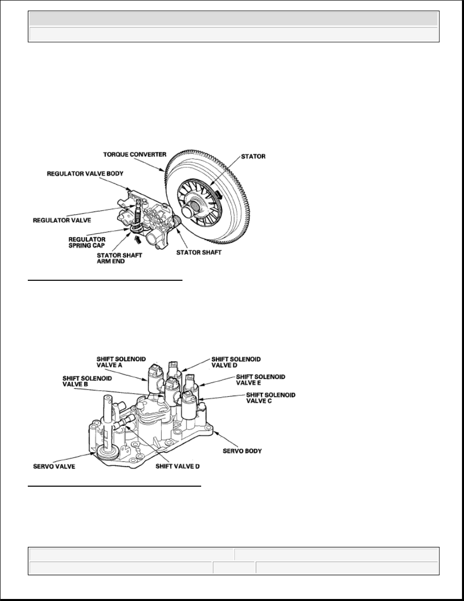
Increases in hydraulic pressure according to torque are regulated by the regulator valve using stator torque 
reaction. The stator shaft is splined with the stator in the torque converter, and its arm end contacts the regulator 
spring cap. When the vehicle is accelerating or climbing (torque converter range), stator torque reaction acts on 
the stator shaft, and the stator arm pushes the regulator spring cap in the direction of the arrow in proportion to 
the reaction. The stator reaction spring compresses, and the regulator valve moves to increase the line pressure 
which is regulated by the regulator valve. The line pressure reaches its maximum when the stator torque 
reaction reaches its maximum. 

Fig. 38: Locating Regulator Spring Cap 
Courtesy of AMERICAN HONDA MOTOR CO., INC. 

Servo Body 

The servo body contains the servo valve, shift valve D, the accumulators for 2nd, 4th, and 5th, and shift 
solenoid valves A, B, C, D, and E. 

Fig. 39: Identifying Servo Body Components 
Courtesy of AMERICAN HONDA MOTOR CO., INC. 

Accumulator 

The accumulators are located in the regulator valve body and the servo body. The regulator valve body contains 
the 1st and 3rd accumulators, and the servo body contains the 2nd, 4th, and 5th accumulators. 


2007 Honda Element EX 

2007-2008 TRANSMISSION Automatic Transmission - Element


Fig. 40: Identifying Accumulator Components 
Courtesy of AMERICAN HONDA MOTOR CO., INC. 

HYDRAULIC FLOW 

Distribution of Hydraulic Pressure 

As the engine turns, the ATF pump starts to operate. Automatic transmission fluid (ATF) is drawn through the 
ATF strainer (filter) and discharged into the hydraulic circuit. Then, ATF flowing from the ATF pump becomes 
line pressure that is regulated by the regulator valve. Torque converter pressure from the regulator valve enters 
the torque converter through the lock-up shift valve, and it is discharged from the torque converter. The torque 
converter check valve prevents torque converter pressure from rising. 

The PCM turns the shift solenoid valves ON and OFF. The shift solenoid valve intercepts line pressure from the 
ATF pump via the manual valve when the shift solenoid valve is OFF. When the shift solenoid valve is turned 
ON, line pressure changes to shift solenoid valve pressure at the shift solenoid valve, then solenoid valve 
pressure flows to the shift valve. Applying shift solenoid pressure to the shift valves moves the position of the 
shift valve, and switches the port of the hydraulic circuit. The PCM also controls A/T clutch pressure control 
solenoid valves A, B, and C. The A/T clutch pressure control solenoid valves regulate hydraulic pressure, and 
apply the pressure to the clutches to engage smoothly. The clutches receive optimum clutch pressure which is 
regulated by the A/T clutch pressure control solenoid valves for comfortable driving and shifting under all 
conditions. 

Hydraulic pressure at the port is as follows:  

HYDRAULIC PRESSURE PORT REFERENCE 

Port No.

Description of Pressure

Port No.

Description of Pressure

1

LINE

SB

SHIFT SOLENOID 
VALVE B

3

LINE

SC

SHIFT SOLENOID 
VALVE C


2007 Honda Element EX 

2007-2008 TRANSMISSION Automatic Transmission - Element


3'

LINE

SD

SHIFT SOLENOID 
VALVE D

4

LINE

SE

SHIFT SOLENOID 
VALVE E

4'

LINE

10

1ST CLUTCH

4"

LINE

20

2ND CLUTCH

7

LINE

30

3RD CLUTCH

1A

LINE or A/T CLUTCH 
PRESSURE CONTROL 
SOLENOID VALVE A

40

4TH CLUTCH

1B

LINE

50

5TH CLUTCH

3A

LINE

55

A/T CLUTCH 
PRESSURE CONTROL 
SOLENOID VALVE A

3B

LINE

55'

A/T CLUTCH 
PRESSURE CONTROL 
SOLENOID VALVE A

3C

LINE

56

A/T CLUTCH 
PRESSURE CONTROL 
SOLENOID VALVE B

5A

LINE

57

A/T CLUTCH 
PRESSURE CONTROL 
SOLENOID VALVE C

5B

LINE

90

TORQUE CONVERTER

5C

LINE

91

TORQUE CONVERTER

5D

LINE

92

TORQUE CONVERTER

5E

LINE or A/T CLUTCH 
PRESSURE CONTROL 
SOLENOID VALVE B

93

ATF COOLER

5F

LINE or A/T CLUTCH 
PRESSURE CONTROL 
SOLENOID VALVE A 
or B

94

TORQUE CONVERTER

5G

A/T CLUTCH 
PRESSURE CONTROL 
SOLENOID VALVE B

95

LUBRICATION

5H

A/T CLUTCH 
PRESSURE CONTROL 
SOLENOID VALVE C

96

TORQUE CONVERTER

5J

A/T CLUTCH 
PRESSURE CONTROL 
SOLENOID VALVE C

97

TORQUE CONVERTER

5K

A/T CLUTCH 
PRESSURE CONTROL 

99

SUCTION


2007 Honda Element EX 

2007-2008 TRANSMISSION Automatic Transmission - Element


N Position 

The PCM controls the shift solenoid valves. The conditions of the shift solenoid valves and positions of the shift 
valves are as follows: 

Shift solenoid valve A: OFF, and shift valve A stays on the right side  

Shift solenoid valve B: ON, and shift valve B moves to the left side  

Shift solenoid valve C: ON, and shift valve C moves to the left side  

Shift solenoid valve D: OFF, and shift valve D stays on the left side  

Shift solenoid valve E: OFF, and shift valve E stays on the left side  

Line pressure (1) flows to the shift solenoid valves and A/T clutch pressure control solenoid valve A. Under this 
condition, hydraulic pressure is not applied to the clutches. 

SOLENOID VALVE C

5L

A/T CLUTCH 
PRESSURE CONTROL 
SOLENOID VALVE C

X

DRAIN

5N

A/T CLUTCH 
PRESSURE CONTROL 
SOLENOID VALVE C

HX

HIGH POSITION DRAIN

SA

SHIFT SOLENOID 
VALVE A

AX

AIR DRAIN

NOTE:

When used, "left" or "right" indicates direction on the hydraulic circuit.


2007 Honda Element EX 

2007-2008 TRANSMISSION Automatic Transmission - Element


Content   ..  186  187  188  189   ..