Honda Element. Manual - part 187
PCM CONNECTOR D (17P)
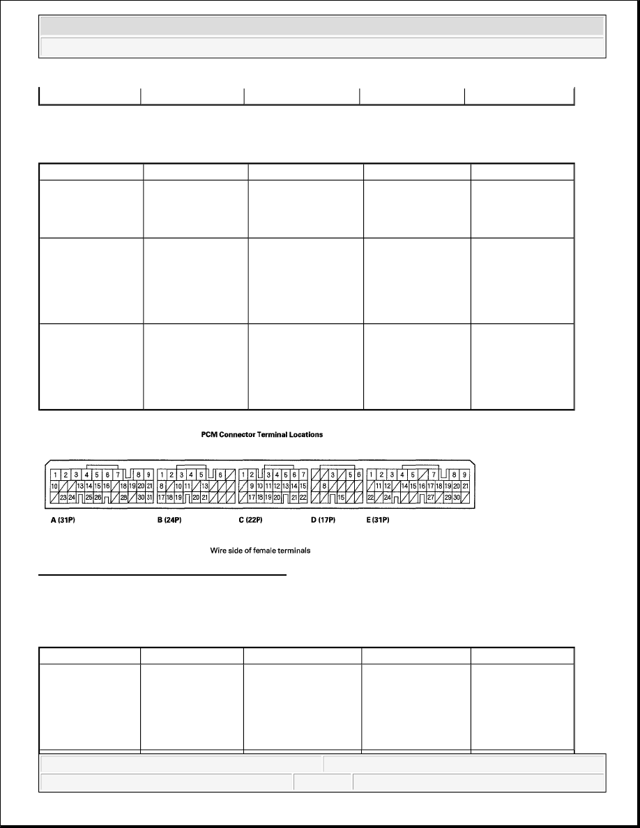
PCM CONNECTOR TERMINAL REFERENCE
Fig. 33: Identifying PCM Connector Terminal
Courtesy of AMERICAN HONDA MOTOR CO., INC.
PCM CONNECTOR E (31P)
PCM CONNECTOR TERMINAL REFERENCE
Battery voltage
Terminal number
Wire color
Terminal name
Description
Signal
D3
GRN
D3 SW(D3 SWITCH) Detects D3 switch
signal
D3 switch ON:
About 0 V
D3 switch OFF:
Battery Voltage
D5
WHT
ATP R
(TRANSMISSION
RANGE SWITCH R)
Detects transmission
range switch R
signal
In R position:
About 0 V
In any position
other than R
position: Battery
voltage
D6
BLK/BLU
ATP P
(TRANSMISSION
RANGE SWITCH P)
Detects transmission
range switch P
signal
In P position:
About 0 V
In any position
other than P
position: Battery
voltage
Terminal number
Wire color
Terminal name
Description
Signal
E2
WHT/BLU
SLS (SHIFT LOCK
SOLENOID)
Drives shift lock
solenoid
With ignition
switch ON (II), in P
position, brake
pedal pressed, and
accelerator closed:
About 0 V
2007 Honda Element EX
2007-2008 TRANSMISSION Automatic Transmission - Element