Great Wall Hover. Manual - part 71
Brake-5
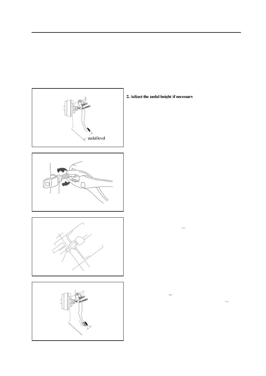
Check and adjustment
Check and adjustment of brake pedal
1. Check the correctness of height of pedal
Distance from pedal to lower front apron: 152mm, Operating stroke
of pedal push bar is 1mm.
a. Disconnect the brake lamp switch wire connector; loose the
tightened nut; rotate the brake switch to the position not contacted
to limit block of brake pedal
b. Loose the lock nut of operating connecting rod; use the thinnose
pliers to rotate the operating connecting rod to adjust the height
of brake pedal to the standard value; lock the block nut tightenedly
when reach the standard value.
c. Rotate the brake lamp switch to contact with the limit block of
brake pedal; then rotate 1/2
1 round continuously; tighten the
block nut;
d. Connect the wire connector of brake lamp switch;
e. The brake lamp should not be light when the brake pedal is
released.
3. Check the free stroke of pedal
Free stroke of pedal: 4
6mm
In the status of engine is stop, step on the brake pedal for 2
3 times
after eliminate effect of the brake assist, push down the brake pedal
by hand to just with the resistance, then measure its displacement
(free stroke). It should be in accordance with the standard value.
pedal push rod
parking lamp switch
free stroke of pedal
pedal push rod