Great Wall Hover. Manual - part 8


  Index      Great Wall     Great Wall Hover - service repair manual


Search            copyright infringement  


Content   ..  6  7  8  9   ..


Great Wall Hover. Manual - part 8


Clutch-9

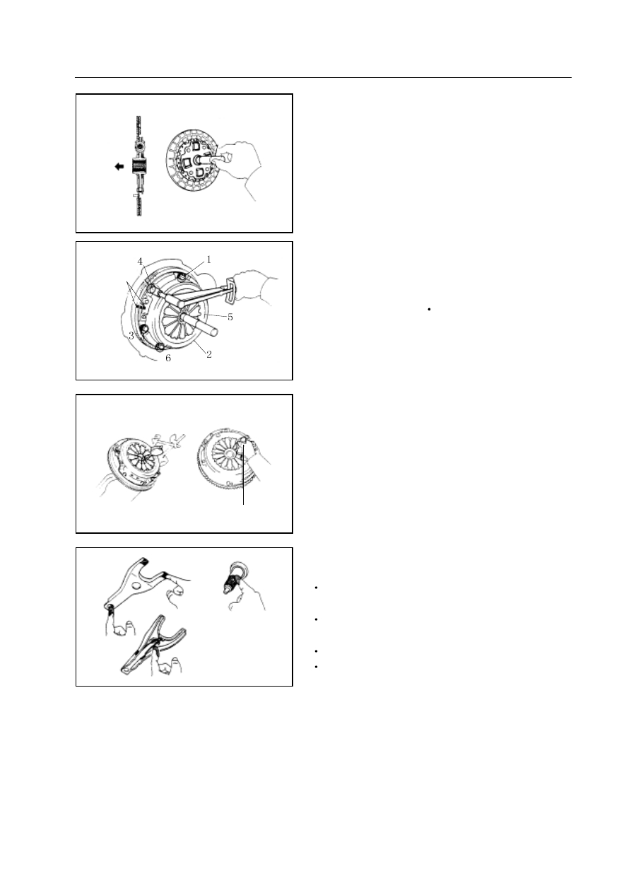
2.Installtion of clutch cover

a. Align the matching mark of clutch shell with that of flywheel .

b. Tighten the bolt evenly. Exert force along the edge of the clutch

cover repeatedly until binding tightly. Tighten the bolt.

Tightening force:   19N

m

Remarks:   First tighten the upper most bolt of the 3 bolts

near the

location pin.

3. Check the end surface runout of diaphragm spring clutch finger.

Use the special tools to check the alignment of diaphragm spring.

Maximum displacement:   0.5mm

If the displacement is greater than the specified value, use the special

tools to adjust the face runout amount of the diaphragm spring clutch

finger.

4. Coat the following components with the molybdenum disulfide

lithium base grease (NLGI NO.2) or multi-purpose grease :

contacting point of separation rocker arm assembly and bearing

bush

contacting point of separation rocker arm assembly and subcylinder

push bar

separation rocker arm assembly supporting point

gear box 1

st

 axle spline

5. Install the leather cup, separation rocker arm assembly, clutch

cover assembly and throwout bearing in the transmission.

6. Install the transmission

matching mark

Installation of clutch

1.Install the clutch disc on the flywheel

Use the special tools to install the clutch disc on the flywheel.

special tools

       Chapter 4

Specification of transmission.......................................................................2

Repair of transmission  (SC5M2D

C).....................................................4

Disassembly of transmission  (SC5M2D

C)............................................6

Disassembly of transmission housing assembly/bearing housing assembly....18

Operating instruction of transmission  (SC5M4D

C).............................24

Repair of transmission  (SC5M4D

C)...................................................25

Disassembly of rear housing assembly ......................................................28

Disassembly of transfer case assembly......................................................30

Rear output shaft assembly .......................................................................35

Structure diagram of SC5M2D-C and SC5M4D-C transmission:   shown in figure

Structure diagram of SC5M2D-C transmission

Structure diagram of SC5M4D-C transmission

Specification of transmission

1. 

Speed ratio of transmissio 


Gear 

Ⅰ 

Ⅱ 

Ⅲ 

Ⅳ 

Ⅴ R 

Speed 

ratio 

3.967 

2.136 1.360 1.000 0.856 3.578 


2. 

Speed ratio of transfer case    SC5M4D-C 


Gear synchronizer     

Speed ratio 

1.000 

1.925 


3.      Central distance of main shaft 

transmission                      72    mm 

transfer case        222.25 mm  

4.    Instruction for repair specification of transmission 


Inspection item 

Repair specification 

End clearance of gear of Axle 1 (mm)   

0~0.06    Adjusted by axial retainer. 

Clearance between bearing block and bearing of Axle 1 (mm)   

0~0.1      Adjusted by adjusting shim. 

End clearance of gear hub of Gear 3/ 4 synchronizer    (mm)   

0~0.08    Adjusted by axial retainer. 

Clearance of rear end cone bearing of intermediate shaft (mm)   

0~0.05    Adjusted by adjusting shim. 

End clearance of gear hub of high and low gear (mm)  

SC5M4D-C 

0~0.08 Adjusted by axial retainer. 

Clearance between the rear output shaft rear bearing    and back 

cover (mm)   SC5M4D-C 

0~0.1      Adjusted by adjusting shim. 

Clearance of rear input shaft bearing (mm)        SC5M4D-C 

0~0.06    Adjusted by adjusting shim.   


Content   ..  6  7  8  9   ..