Ford Festiva. Instruction - part 8


  Index      Ford     Ford Festiva - service and repair instruction 1991 year


Search            


Content   ..  6  7  8  9   ..


Ford Festiva. Instruction - part 8


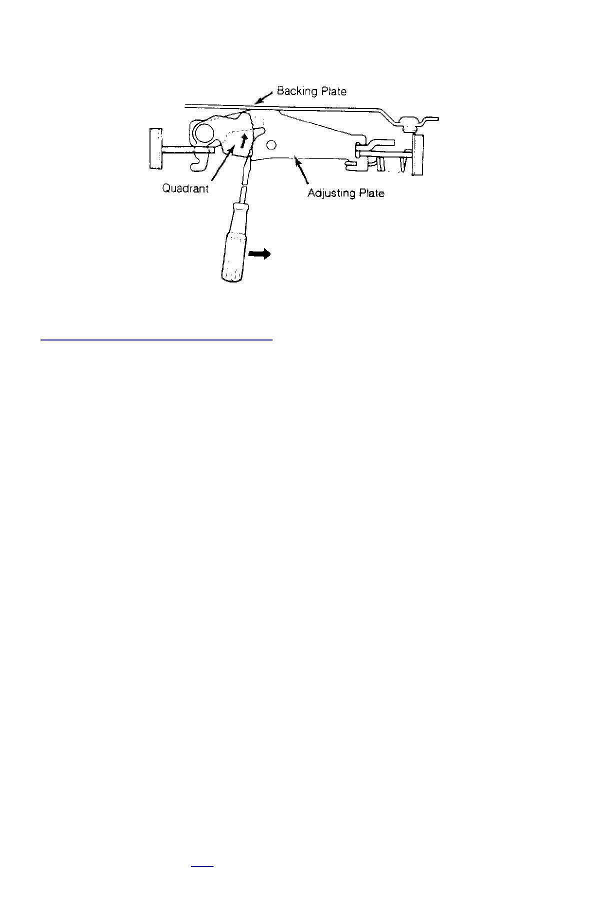
Fig. 2: Moving Quadrant on Drum Brake Adjuster (Festiva)


Courtesy of FORD MOTOR CO. 

FRONT AXLE BEARINGS 

Front bearing preload is adjusted during bearing replacement by changing preload spacer. See FRONT WHEEL BEARINGS under 
REMOVAL & INSTALLATION. 

REAR AXLE BEARINGS 

With bearings installed, tighten NEW lock nut to 18-22 ft. lbs. (24-30 N.m) while rotating wheel. Slightly loosen lock nut so it can be turned 
by hand. Install a lug nut into axle hub. Attach an inch-pound torque wrench to lug nut at 12 o'clock position. Measure bearing preload. 
Tighten lock nut until bearing preload, including seal drag, is 3.5-6.2 INCH lbs. (.4-.7 N.m). Stake NEW lock nut into notch on spindle. 

TESTING 

POWER BRAKE UNIT 

Functional Test 

1. Check master cylinder fluid level and hydraulic system for leaks. Place transaxle in Neutral or Park, turn ignition off and apply parking 

brake. Pump brake pedal several times to eliminate vacuum from system, and hold pedal in depressed position.  

2. Start and idle engine. If vacuum system is functioning properly, pedal moves downward under constant foot pressure. If no pedal motion 

is felt, vacuum booster is not functioning properly. Go to next step.  

3. Run engine for at least one minute and turn ignition off. Depress brake pedal several times. Booster is okay if pedal stroke is long at first 

and becomes shorter with each stroke. If stroke does not shorten, check for a damaged, restricted or improperly connected check valve 
vacuum hose. Repair and recheck. Go to next step.  

4. Restart engine. Depress and hold pedal down. Turn ignition off and wait 30 seconds. Booster is okay if pedal height remains unchanged. 

If pedal height changes, check for a damaged, restricted or improperly connected check valve or vacuum hose. Go to next step.  

5. Connect a pressure gauge to master cylinder output line. Connect a vacuum gauge to booster and a pedal depression force gauge to 

brake pedal. Bleed air from pressure gauge. Start engine. When vacuum gauge reads 19.7 in. Hg, turn ignition off. Watch vacuum gauge 
for 15 seconds. Booster is okay if vacuum gauge reads 18.7-19.7 in. Hg. If vacuum gauge reads less than 18.7 in. Hg, proceed to next 
step.  

6. Restart engine. Apply and hold 44 lbs. (196 N) force to brake pedal. When vacuum gauge reading reaches 19.7 in. Hg, turn ignition off. 

Watch vacuum gauge for 15 seconds. Booster is okay if vacuum gauge reads 18.7-19.7 in. Hg. If vacuum gauge reads less than 18.7 in. 
Hg, proceed to next step.  

7. With engine stopped and vacuum gauge at zero, check pressure gauge. Apply 44 lbs. (196 N) force to brake pedal and check pressure 

gauge. Booster is okay if pressure gauge reads 256 psi (18 kg/cm

2

 ).  

8. Remove pedal force and start engine. When vacuum gauge reaches 19.7 in. Hg, apply 44 lbs. (196 N) force to pedal. Booster is okay if 

pressure gauge read 768 psi (54 kg/cm

2

 ).  

Diagnosis 

If booster does not function properly, see 

Fig. 3

 . 

NOTE:

Axle lock nut on right side has left-hand threads. Always install NEW lock nut when removed.

NOTE:

Inspect all vacuum hoses for holes, collapsed areas and secure connections. Ensure all unused 
vacuum ports are capped.


Fig. 3: Power Brake Unit Troubleshooting


CHECK VALVE 

On Capri, check valve is located on power brake unit. On Festiva, check valve is located in vacuum hose connecting power booster to intake 
manifold. Disconnect check valve vacuum hose from manifold. Alternately apply vacuum and pressure to hose. Ensure air flows only toward 
engine. If pressure by-passes check valve or if check valve blocks vacuum, replace hose and check valve. 

REMOVAL & INSTALLATION 

FRONT BRAKE CALIPER & PADS 

Removal & Installation (Capri) 

1. Raise and support front of vehicle. Remove wheels. Using needle-nose pliers, remove brake pad pin retainer spring. Remove brake pad 

pins. Remove brake pads and shims. Mark shims so they can be reinstalled in their original position. DO NOT discard shims from inner 
brake pad.  

2. Remove flex hose-to-caliper banjo bolt. Remove caliper retaining bolts and caliper. To install, reverse removal procedure. Ensure brake 

pad shims are installed behind inner brake pad.  

Removal & Installation (Festiva) 

1. Raise and support front of vehicle. Remove wheels. Remove brake pad pin retainer clip. Remove brake pad pins and anti-rattle spring. 

Remove brake pads and shims. Mark shims so they can be reinstalled in their original position. DO NOT discard shims from inner brake 
pad.  

2. To install, reverse removal procedure. Ensure brake pad shims are installed behind inner brake pad.  

FRONT BRAKE ROTOR & HUB 

Removal 

1. Raise and support front of vehicle. Remove wheel. Unstake axle shaft lock nut tab. Apply brakes (to lock hub) and remove drive shaft 

NOTE:

On Festiva, check valve is pressed into hose. An arrow on hose indicates direction of vacuum flow.

NOTE:

Front knuckle, disc brake rotor and hub are removed as an assembly.

lock nut. Discard axle lock nut. Separate tie rod end from knuckle. 

2. Disconnect brake hose from strut (if necessary). Remove brake caliper assembly from knuckle and wire out of way. Remove nuts and 

bolts holding ball joint and strut to knuckle assembly.  

3. Remove knuckle assembly from ball joint and drive shaft. If binding occurs, use a dual-jawed puller to force knuckle/hub/rotor assembly 

off drive axle shaft. 

4. Using a puller, separate knuckle from wheel hub. Retain original outer bearing preload spacer to maintain bearing preload setting. If 

replacing bearing, change spacer to maintain proper bearing preload (if necessary). See FRONT WHEEL BEARINGS under REMOVAL 
& INSTALLATION. Scribe match marks between hub and rotor assembly. Remove rotor-to-hub bolts. Separate hub from rotor.  

Installation 

Align marks and install rotor on hub. Press knuckle and preload spacer into wheel hub assembly. To complete installation, reverse removal 
procedure. Tighten axle shaft lock nut to 117-175 ft. lbs. (159-237 N.m). 

REAR BRAKE CALIPER & PADS 

Removal (Capri) 

1. Raise and support vehicle. Remove tire and wheel assembly. Using needle-nose pliers, remove parking brake return spring. Loosen 

parking brake cable housing adjusting nut. Remove cable housing from bracket on lower control arm. Loosen parking brake cable 
bracket-to-caliper attaching bolt. Remove parking brake cable from caliper.  

2. Remove lower caliper retaining bolt. Pivot caliper upward on upper caliper guide pin. Remove brake pad retaining spring, pads and 

shims. If replacing rear brake pads only, reverse removal procedure to install. If removing caliper, proceed to next step.  

3. Remove attaching clip from brake flex hose. Remove flex hose banjo bolt from caliper and discard copper washers. Remove lower 

caliper retaining bolt. Using a cold chisel, remove upper caliper guide pin dust cap. Using an Allen wrench, remove upper caliper guide 
pin. Lift caliper off rotor.  

Installation 

1. To install, fit brake pads and shims into caliper anchor plate. Remove upper guide pin and lower guide pin bushing from caliper. 

Remove guide pin and guide pin bushing dust boots. Lubricate upper guide pin and lower guide pin bushing with Disc Brake Caliper 
Slide Grease (D7AZ-19590-A).  

2. To complete installation, reverse removal procedure. To fit caliper over new brake pads, it may be necessary to rotate caliper piston into 

caliper bore. Use NEW copper washers on flex hose. Bleed brakes, and then pump brake pedal several times to seat pads.  

REAR BRAKE ROTOR 

Removal & Installation (Capri) 

See REAR WHEEL BEARINGS under REMOVAL & INSTALLATION. 

REAR BRAKE SHOES 

Removal & Installation (Festiva) 

Remove brake drum. Remove hold-down springs. Remove return springs. Remove self adjuster. See 

Fig. 8

 . To install, reverse removal 

procedure. Apply brake grease to all shoe contact points. See REAR BRAKE SHOES under ADJUSTMENTS. 

REAR WHEEL CYLINDER 

Removal & Installation (Festiva) 

Remove rear brake shoes. Disconnect brake line from wheel cylinder. Remove wheel cylinder. To install, reverse removal procedure. Bleed 
brake system. 

MASTER BRAKE CYLINDER 

Removal 

Disconnect low fluid level sensor wiring (if equipped). Drain some brake fluid from reservoir. Disconnect brake lines from master cylinder. 
Cap lines and master cylinder ports. Remove attaching nuts and master cylinder. 

Installation 

To install, reverse removal procedure. Fill master cylinder to proper level and bleed hydraulic system (if necessary). 

POWER BRAKE UNIT 

Removal & Installation 

Remove master cylinder. Disconnect vacuum line. Remove clevis pin at brake pedal. Remove power brake unit. To install, reverse removal 
procedure. 

FRONT WHEEL BEARINGS 

NOTE:

Hub and rotor are a matched and balanced assembly. Before removing rotor, locate paint or etch 
mark indicating proper hub-to-rotor alignment. If marks are not present, mark hub and rotor for 
assembly alignment. Failure to properly align hub and rotor can result in an imbalance condition.

Removal 

Remove rotor and hub assembly from steering knuckle. Separate rotor, knuckle and hub. See FRONT BRAKE ROTOR & HUB under 
REMOVAL & INSTALLATION. Press outer bearing from hub using Bearing Splitter (D84L-1123-A) and Shaft Protector (D80L-625-2). 
Remove and discard outer grease seal. Pry inner wheel bearing grease seal from steering knuckle using a large screwdriver. Discard seal. 
Remove inner bearing. 

Bearing Preload 

1. Use Spacer Selector Set (T87C-1104-B) to check and adjust preload. Install spacer selector into steering knuckle and clamp tool in vise 

where shock absorber mounts, before installing hub/rotor assembly into steering knuckle. See 

Fig. 4

 . 


Fig. 4: Installing Preload Spacer Selector Set


Courtesy of FORD MOTOR CO. 

2. Tighten center bolt from spacer selector set, in increments, to 36, 72, 108 and finally 145 ft. lbs. (49, 98, 147 and 196 N.m). Each time 

center bolt is tightened, seat bearings by rotating hub by hand. Using an inch-pound torque wrench, measure torque required to turn 
center bolt. Ensure torque reading is taken just as wrench starts to rotate.  

3. Preload spacer thickness is correct if torque wrench indicates 2.2-16 INCH lbs. (.25-1.8 N.m). If measurement indicates less than 2.2 

INCH lbs. (.25 N.m), a thinner spacer must be installed. If measurement indicates more than 16 INCH lbs. (1.8 N.m), a thicker spacer 
must be installed.  

4. Bearing spacers are available in various thicknesses. See PRELOAD SPACER AVAILABILITY table. Changing spacer thickness one 

number changes bearing preload 1.8-3.5 INCH lbs. (.2-.4 N.m). Ensure correct spacer is installed and preload is within specification. 
Remove preload spacer selector set.  

PRELOAD SPACER AVAILABILITY 

Stamped Mark On Spacer

In. (mm)

1

0.2474 (6.285)

2

0.2490 (6.325)

3

0.2506 (6.365)

4

0.2522 (6.405)

5

0.2537 (6.445)

6

0.2553 (6.485)

7

0.2569 (6.525)

8

0.2585 (6.565)

9

0.2600 (6.605)

10

0.2616 (6.645)

11

0.2632 (6.685)

12

0.2648 (6.725)

13

0.2663 (6.765)

14

0.2679 (6.805)

15

0.2695 (6.845)

16

0.2711 (6.885)


Content   ..  6  7  8  9   ..