Ford Festiva. Instruction - part 7


  Index      Ford     Ford Festiva - service and repair instruction 1991 year


Search            


Content   ..  5  6  7  8   ..


Ford Festiva. Instruction - part 7


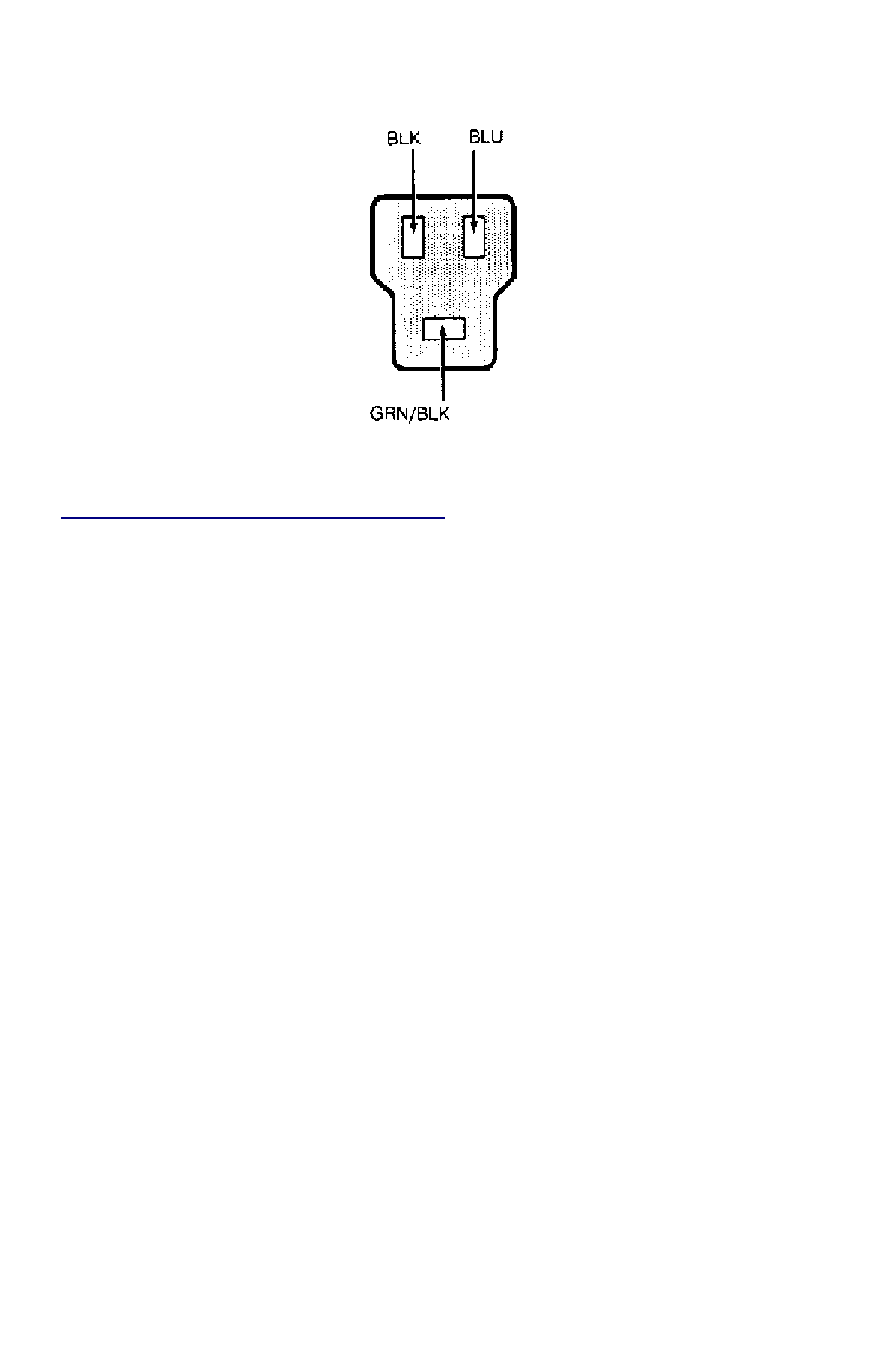
Fig. 3: Identifying Rear Wiper/Washer Switch Terminals (Festiva)


Courtesy of FORD MOTOR CO. 

REAR WASHER MOTOR TEST 

See FRONT WASHER MOTOR TEST under TESTING. 

REMOVAL & INSTALLATION 

FRONT WIPER MOTOR 

Removal 

Disconnect negative battery cable. On Capri, gently pry linkage off ball socket at wiper motor arm. On Festiva, remove access plate then gently 
pry linkage off ball socket at wiper motor arm. On all models, disconnect wiper motor electrical connector. Remove 4 mounting bolts and 
rubber insulators and remove wiper motor. 

Installation 

Position wiper motor on firewall. Install 4 rubber insulators and mounting screws and tighten to 62-89 INCH lbs. (7-10 N.m). Reverse removal 
procedure to complete installation. Check wipers for proper operation. 

FRONT WIPER/WASHER SWITCH 

Removal & Installation (Capri) 

Remove center trim panel and access cover under steering column. Remove 2 screws and remove lower steering column shroud. Disconnect 
wiper/washer switch electrical connector and pull wiring from routing clip. Firmly grasp switch and lever and remove from mounting. To 
install, reverse removal procedure. 

Removal & Installation (Festiva) 

1. Disconnect negative battery cable. From back of steering wheel, remove 2 screws securing horn pad. Disconnect horn wire from horn 

pad and remove pad. Remove steering wheel nut. Scribe reference mark on steering shaft and steering wheel hub for reassembly. Using 
Steering Wheel Puller (T67L-3600-A), remove steering wheel.  

2. Remove 4 screws from upper half of lower steering column cover. Remove cover. Remove upper steering column cover. Remove 5 clips 

from lower half of lower steering column cover. Remove cover.  

3. Release wiring harness clip and unplug 4 harness connectors from back of combination switch. From below steering column, loosen 

band clamp securing switch hub to steering column jacket. Pull switch assembly from steering column.  

4. To install, slide combination switch assembly onto steering column. Make sure switch assembly is seated and level against end of 

column jacket. To complete installation, reverse removal procedure.  

FRONT WASHER MOTOR & RESERVOIR 

Removal & Installation (Capri) 

Drain reservoir if necessary. Remove 2 bolts securing reservoir to inner finder. Disconnect electrical connector from washer pump motor. 

NOTE:

Disconnect linkage from wiper motor arm ball socket NOT by removing nut and wiper motor arm. This 
will eliminate the need to retime wiper motor and linkage. Replacement motors are supplied with arm 
attached. Manufacturer does not give procedure for timing motor arm to wiper park position.

Disconnect fluid lines and remove reservoir. To install, reverse removal procedure.

Removal & Installation (Festiva) 

1. Disconnect negative battery cable. Remove washer reservoir filler neck attaching bolt. Remove coolant expansion reservoir. Disconnect 

washer pump electrical connector. Remove left front splash shield.  

2. Disconnect washer pump fluid lines and detach lines from reservoir clips. Remove reservoir attaching nuts and bolt. Detach washer 

reservoir from filler neck and remove reservoir. To install, reverse removal procedure.  

REAR WIPER MOTOR 

Removal & Installation (Festiva) 

Remove rear wiper arm and blade assembly. Remove boot from outer bushing attaching nut. Remove outer bushing attaching nut and remove 
outer bushing. Remove liftgate trim panel. Disconnect wiper motor electrical connector. Remove 4 wiper motor mounting bolts and remove 
motor. To install, reverse removal procedure. 

REAR WIPER/WASHER SWITCH 

Removal & Installation (Festiva) 

Disconnect negative battery cable. Remove steering column covers. Remove screws securing instrument panel bezel to instrument panel. Pull 
instrument bezel away from instrument panel. Disconnect electrical connectors from switches in bezel. Compress wiper/washer switch lock 
tabs and remove switch from bezel. To install, reverse removal procedure. 

REAR WASHER MOTOR & RESERVOIR 

Removal & Installation (Festiva) 

Open liftgate and detach reservoir cap. Remove rear quarter trim panel. Remove reservoir mounting bolts. Disconnect electrical connector 
from washer pump. Disconnect fluid lines. Remove reservoir. To install, reverse removal procedure. 

TORQUE SPECIFICATIONS 

TORQUE SPECIFICATIONS 

WIRING DIAGRAMS 

See appropriate chassis wiring diagram in the WIRING DIAGRAMS Section. 

Application

INCH Lbs. (N.m)

Front Wiper Arm Retaining Nut

89-124 (10-14)

Front Wiper Motor Mounting Bolts

62-89 (7-10)

Rear Outer Bushing Retaining Nut

27-44 (3-5)

Rear Wiper Arm Nut

53-62 (6-7)

Rear Wiper Motor Mounting Bolts

71-97 (8-11)

Copyright 2009 Mitchell Repair Information Company, LLC.  All Rights Reserved. 


Article GUID: A00028304 

Back To Article


BRAKE SYSTEM

1991-92 BRAKES Disc & Drum 

DESCRIPTION & OPERATION 

On Capri, vehicle braking is provided by front and rear disc brakes. Front and rear brakes are a full-floating, single piston design. The rear 
caliper houses a self-adjusting parking brake. 

On Festiva, vehicle braking is provided by front disc brakes and rear drum brakes. Rear brakes are a standard non-servo, self-energizing design. 
Front brakes are a full-floating, single piston design with caliper attached to steering knuckle. 

BLEEDING BRAKE SYSTEM 

BLEEDING PROCEDURES 

Instruction Bleeding 

1. Exhaust vacuum from power brake unit by depressing brake pedal several times. Fill master cylinder with clean brake fluid. Install clear 

vinyl bleeder hose onto first bleeder valve to be serviced. See BRAKE LINE BLEEDING SEQUENCE table. Place other end of hose in 
clean transparent container.  

2. Partially fill container with clean brake fluid. Open the bleeder valve 3/4 turn. Slowly depress brake pedal through its full travel. Close 

bleeder valve and release pedal. Pump pedal several times to push air toward wheel cylinders. Repeat procedure until flow of brake 
fluid is clear and shows no signs of air bubbles. Proceed to next bleeder valve in sequence and repeat procedure.  

BRAKE LINE BLEEDING SEQUENCE 

Pressure Bleeding 

1. Exhaust vacuum from power brake unit by depressing brake pedal several times. Fill master cylinder with clean brake fluid. With 

pressure bleeder at least 1/2 full, connect pressure bleeder to master cylinder using appropriate adaptor.  

2. Install clear vinyl bleeder hose onto first bleeder valve to be serviced. See BRAKE LINE BLEEDING SEQUENCE table. Place other 

end of hose in clean transparent container. Partially fill container with clean brake fluid. Open bleeder valve 1-2 turns. Allow fluid to 
run until flow of fluid is clear and shows no signs of air bubbles. Proceed to next bleeder valve in sequence and repeat procedure. 
Remove pressure bleeder and fill master cylinder with clean brake fluid.  

ADJUSTMENTS 

BRAKE PEDAL HEIGHT (FESTIVA) 

1. Block wheels to prevent vehicle from rolling. Start engine and place transmission in Neutral. Fully release parking brake. Move carpet 

and insulation away from firewall and brake pedal. Measure distance horizontally between upper center of brake pedal pad and firewall. 
Distance should be 8.03-8.23" (204-209 mm).  

2. If pedal height is incorrect, inspect pedal assembly for missing, worn or damaged bushings or for loose attaching bolts. Ensure firewall is 

not distorted and pedal is not bent. If pedal height is still not within specifications, check brake pedal, booster or master cylinder for 
correct and/or correctly installed parts  

BRAKE PEDAL FREE PLAY (FESTIVA) 

Pump brake pedal several to bleed vacuum from power brake booster. Gently depress brake pedal by hand and measure and measure play 
before resistance is felt. Free play should be .16-.28" (4-7 mm). If free play is not within specifications, adjust brake pedal push rod. 

BRAKE PEDAL FLOOR CLEARANCE 

Capri 

1. Move carpet and insulation away from floor board and brake pedal. With engine running and using Brake Pedal Effort Gauge (021-

00001), apply 132 lbs. (59.9 kg) of force to brake pedal. Measure distance from upper surface of brake pedal pad to floor board. If 
distance is less than 3.27" (83 mm), inspect pedal assembly for missing, worn or damaged bushings or for loose attaching bolts.  

2. Verify that floor board is not distorted and pedal is not bent. If pedal height is still not within specifications, check brake pedal, booster 

or master cylinder for correct and/or correctly installed parts. Check for air in hydraulic system.  

Festiva 

Move carpet and insulation away from floor board and brake pedal. Using Brake Pedal Effort Gauge (021-00001) or equivalent, apply 132 
lbs. (59.9 kg) of force to brake pedal. Measure distance from upper surface of brake pedal pad to floor board. If distance is less than 2.68" (68 
mm), check for air in hydraulic system, faulty automatic adjusters or excessive shoe clearance. 

POWER BRAKE UNIT PUSH ROD 

Capri 

Application

Sequence

Capri

RR, LF, LR & RF

Festiva

RR, LR, RF & LF

NOTE:

Check fluid level in master cylinder frequently during the bleeding sequence.

Power brake push rod length is not adjustable.

Festiva 

Remove master cylinder. See MASTER BRAKE CYLINDER under REMOVAL & INSTALLATION. Place Adjustment Gauge (T87C-2500-
A) on master cylinder. Loosen set screw on gauge and place plunger against master cylinder. See 

Fig. 1

 . Invert gauge and position on power 

booster. Check clearance between gauge and power booster. Adjust push rod until clearance is zero. 


Fig. 1: Measuring Brake Booster Push Rod Length (Festiva)


Courtesy of FORD MOTOR CO. 

PARKING/EMERGENCY BRAKE 

Capri 

1. Ensure parking brake lever is released. Remove parking brake console. Loosen parking brake cable lock nut. Loosen or tighten adjusting 

nut so parking brake begins to apply when lever is pulled up 5 notches and is fully applied at 7-11 notches.  

2. Using Spring Scale (T74P-3504-Y), check force required to apply parking brake. A properly operating system will require 44 lb. (97 kg) 

of force to fully apply parking brakes. Tighten lock nut. Ensure brake warning light operates when parking brake lever is raised.  

Festiva 

1. Ensure parking brake lever is released. Remove parking brake console insert. Remove locking clip from cable adjuster nut. Raise and 

support rear of vehicle. Tighten parking brake adjuster until slight drag is felt when rotating wheels.  

2. Loosen adjuster in small increments until drag is eliminated. As parking brake lever is lifted, parking brake should lock rear wheels in 

11-16 notches. Ensure brake warning light operates when parking brake lever is raised.  

REAR BRAKE SHOES 

Festiva 

1. Raise and support vehicle. Release parking brake. Unstake and remove axle lock nut. Remove brake drum. Insert screwdriver between 

adjusting plate and quadrant. See 

Fig. 2

 . Twist screwdriver to disengage teeth.  

2. Push quadrant adjusting lever toward backing plate. Install brake drum and NEW axle lock nut. Adjust wheel bearings and secure nut 

by crimping. See REAR AXLE BEARINGS. Operate brake pedal a few times to reset adjuster. Adjust parking brake (if necessary). See 
PARKING/EMERGENCY BRAKE.  


Content   ..  5  6  7  8   ..