Dodge Sprinter. Manual - part 303


  Index      Dodge     Dodge Sprinter / Mercedes-Benz - service repair manual 2006 year


Search            


Content   ..  301  302  303  304   ..


Dodge Sprinter. Manual - part 303


• Transmission fluid temperature

• Engine coolant temperature

• Input speed

• Throttle angle

• Engine speed

OPERATION

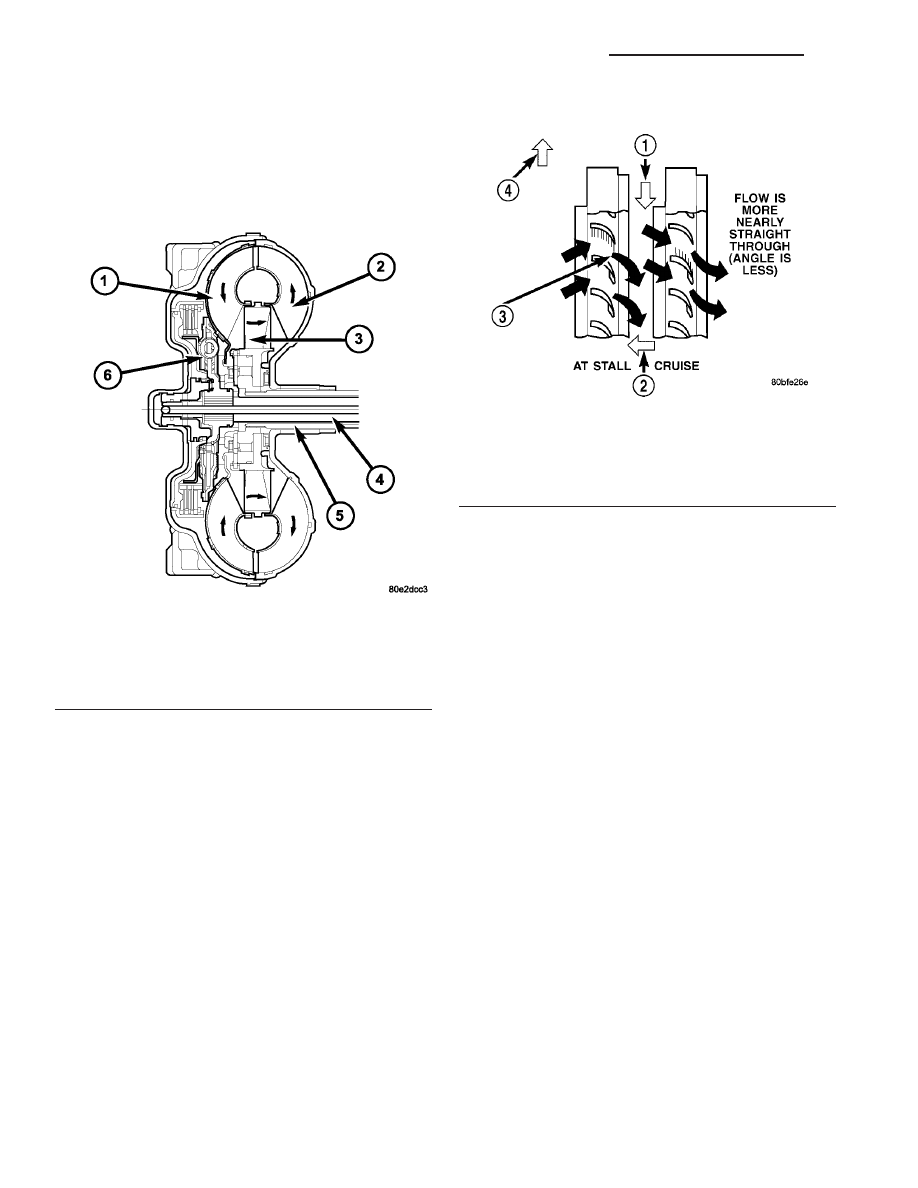
The converter impeller (driving member) (2) (Fig.

248), which is integral to the converter housing and
bolted to the engine drive plate, rotates at engine
speed. The converter turbine (driven member) (1),
which reacts from fluid pressure generated by the
impeller, rotates and turns the transmission input
shaft (4).

TURBINE

As the fluid that was put into motion by the impel-

ler blades strikes the blades of the turbine, some of
the energy and rotational force is transferred into the
turbine and the input shaft. This causes both of them
(turbine and input shaft) to rotate in a clockwise
direction following the impeller. As the fluid is leav-
ing the trailing edges of the turbine’s blades it con-
tinues in a “hindering” direction back toward the
impeller. If the fluid is not redirected before it strikes
the impeller, it will strike the impeller in such a
direction that it would tend to slow it down.

STATOR

Torque multiplication is achieved by locking the

stator’s over-running clutch to its shaft. (Fig. 249)
Under stall conditions (the turbine is stationary), the
oil leaving the turbine blades strikes the face of the
stator blades and tries to rotate them in a counter-
clockwise direction. When this happens the over-run-
ning clutch of the stator locks and holds the stator
from rotating. With the stator locked, the oil strikes
the stator blades and is redirected into a “helping”
direction before it enters the impeller. This circula-
tion of oil from impeller to turbine, turbine to stator,
and stator to impeller, can produce a maximum
torque multiplication of about 2.0:1. As the turbine
begins to match the speed of the impeller, the fluid
that was hitting the stator in such as way as to
cause it to lock-up is no longer doing so. In this con-
dition of operation, the stator begins to free wheel
and the converter acts as a fluid coupling.

Fig. 248 Torque Converter

1 - TURBINE
2 - IMPELLER
3 - STATOR
4 - INPUT SHAFT
5 - STATOR SHAFT
6 - TURBINE DAMPER

Fig. 249 Stator Operation

1 - DIRECTION STATOR WILL FREE WHEEL DUE TO OIL
PUSHING ON BACKSIDE OF VANES
2 - FRONT OF ENGINE
3 - INCREASED ANGLE AS OIL STRIKES VANES
4 - DIRECTION STATOR IS LOCKED UP DUE TO OIL PUSHING
AGAINST STATOR VANES

21 - 182

AUTOMATIC TRANSMISSION NAG1 - SERVICE INFORMATION

VA

TORQUE CONVERTER CLUTCH (TCC)

In a standard torque converter, the impeller (2)

and turbine (1) are rotating at about the same speed
and the stator (3) is freewheeling, providing no
torque multiplication. By applying the turbine’s pis-
ton and friction material (9) (Fig. 250), a total con-
verter engagement can be obtained. The result of this
engagement is a direct 1:1 mechanical link between
the engine and the transmission.

The clutch can be engaged in second, third, fourth,

and fifth gear ranges.

The TCM controls the torque converter by way of

internal logic software. The programming of the soft-
ware provides the TCM with control over the torque
converter solenoid. There are four output logic states
that can be applied as follows:

• No EMCC

• Partial EMCC

• Full EMCC

• Gradual-to-no EMCC

NO EMCC

Under No EMCC conditions, the TCC Solenoid is

OFF. There are several conditions that can result in

NO EMCC operations. No EMCC can be initiated
due to a fault in the transmission or because the
TCM does not see the need for EMCC under current
driving conditions.

PARTIAL EMCC

Partial EMCC operation modulates the TCC Sole-

noid (duty cycle) to obtain partial torque converter
clutch application. Partial EMCC operation is main-
tained until Full EMCC is called for and actuated.
During Partial EMCC some slip does occur. Partial
EMCC will usually occur at low speeds, low load and
light throttle situations.

FULL EMCC

During Full EMCC operation, the TCM increases

the TCC Solenoid duty cycle to full ON after Partial
EMCC control brings the engine speed within the
desired slip range of transmission input speed rela-
tive to engine rpm.

GRADUAL - TO - NO EMCC

This operation is to soften the change from Full or

Partial EMCC to No EMCC. This is done at mid-
throttle by decreasing the TCC Solenoid duty cycle.

REMOVAL

(1) Remove transmission and torque converter

from vehicle.

(2) Place a suitable drain pan under the converter

housing end of the transmission.

CAUTION: Verify that transmission is secure on the
lifting device or work surface, the center of gravity
of the transmission will shift when the torque con-
verter is removed creating an unstable condition.
The torque converter is a heavy unit. Use caution
when separating the torque converter from the
transmission.

(3) Pull the torque converter forward until the cen-

ter hub clears the oil pump seal.

(4) Separate the torque converter from the trans-

mission.

Fig. 250 Torque Converter Lock-up Clutch

1 - TURBINE
2 - IMPELLER
3 - STATOR
4 - INPUT SHAFT
5 - STATOR SHAFT
6 - PISTON
7 - COVER SHELL
8 - INTERNALLY TOOTHED DISC CARRIER
9 - CLUTCH PLATE SET
10 - EXTERNALLY TOOTHED DISC CARRIER
11 - TURBINE DAMPER

VA

AUTOMATIC TRANSMISSION NAG1 - SERVICE INFORMATION

21 - 183

INSTALLATION

Check converter hub and drive flats for sharp

edges, burrs, scratches, or nicks. Polish the hub and
flats with 320/400 grit paper or crocus cloth if neces-
sary. The hub must be smooth to avoid damaging the
pump seal at installation.

(1) Lubricate oil pump seal lip with transmission

fluid.

(2) Place torque converter in position on transmission.

CAUTION: Do not damage oil pump seal or con-
verter hub while inserting torque converter into the
front of the transmission.

(3) Align torque converter to oil pump seal open-

ing.

(4) Insert torque converter hub into oil pump.
(5) While pushing torque converter inward, rotate

converter until converter is fully seated in the oil
pump gears.

(6) Check converter seating with a scale and

straightedge (Fig. 251). Surface of converter lugs
should be at least 19 mm (3/4 in.) to rear of straight-
edge when converter is fully seated.

(7) If necessary, temporarily secure converter with

C-clamp attached to the converter housing.

(8) Install the transmission in the vehicle.
(9) Fill the transmission with the recommended

fluid.

TORQUE CONVERTER HUB
SEAL

REMOVAL

(1) Remove the torque converter (Refer to 21 -

TRANSMISSION/AUTOMATIC

-

NAG1/TORQUE

CONVERTER - REMOVAL).

(2) Remove the torque converter hub seal with

suitable screw and slide hammer.

INSTALLATION

(1) Position the torque converter hub seal (1) (Fig.

252) over the input shaft and against the transmis-
sion oil pump.

(2) Using Seal Installer 8902A (2) (Fig. 253),

install a new torque converter hub seal.

(3) Install the torque converter (Refer to 21 -

TRANSMISSION/AUTOMATIC

-

NAG1/TORQUE

CONVERTER - INSTALLATION).

Fig. 251 Torque Converter Installation Depth

1 - TORQUE CONVERTER
2 - TRANSMISSION HOUSING

Fig. 252 Position Torque Converter Hub Seal

1 - TORQUE CONVERTER HUB SEAL
2 - INPUT SHAFT

Fig. 253 Install Torque Converter Hub Seal

1 - OIL PUMP
2 - SEAL INSTALLER 8902A

21 - 184

AUTOMATIC TRANSMISSION NAG1 - SERVICE INFORMATION

VA

TIRES / WHEELS

TABLE OF CONTENTS

page

page

TIRES/WHEELS

DIAGNOSIS AND TESTING - TIRE AND

WHEEL RUNOUT

. . . . . . . . . . . . . . . . . . . . . . 1

STANDARD PROCEDURE

STANDARD PROCEDURE - MATCH

MOUNTING . . . . . . . . . . . . . . . . . . . . . . . . . . . 2

STANDARD PROCEDURE - TIRE AND

WHEEL BALANCE . . . . . . . . . . . . . . . . . . . . . . 4

STANDARD PROCEDURE - TIRE ROTATION

. 6

SPECIFICATIONS

TORQUE CHART

. . . . . . . . . . . . . . . . . . . . . . 7

TIRES

DESCRIPTION

DESCRIPTION - TIRES

. . . . . . . . . . . . . . . . . . 7

DESCRIPTION - RADIAL – PLY TIRES

. . . . . . 7

DESCRIPTION - TIRE PRESSURE FOR

HIGH SPEEDS . . . . . . . . . . . . . . . . . . . . . . . . . 8

DESCRIPTION - REPLACEMENT TIRES

. . . . . 8

DESCRIPTION - TIRE INFLATION

PRESSURES . . . . . . . . . . . . . . . . . . . . . . . . . . 8

DIAGNOSIS AND TESTING

DIAGNOSIS AND TESTING - PRESSURE

GAUGES . . . . . . . . . . . . . . . . . . . . . . . . . . . . . 9

DIAGNOSIS AND TESTING - TIRE NOISE

OR VIBRATION . . . . . . . . . . . . . . . . . . . . . . . . 9

DIAGNOSIS AND TESTING - TREAD WEAR

INDICATORS . . . . . . . . . . . . . . . . . . . . . . . . . . 9

DIAGNOSIS AND TESTING - TIRE WEAR

PATTERNS . . . . . . . . . . . . . . . . . . . . . . . . . . . 9

DIAGNOSIS AND TESTING - TIRE/VEHICLE

LEAD . . . . . . . . . . . . . . . . . . . . . . . . . . . . . . . 10

STANDARD PROCEDURE - REPAIRING

LEAKS

. . . . . . . . . . . . . . . . . . . . . . . . . . . . . . 12

CLEANING

. . . . . . . . . . . . . . . . . . . . . . . . . . . . 12

SPECIFICATIONS

TIRES

. . . . . . . . . . . . . . . . . . . . . . . . . . . . . . 12

SPARE TIRE CARRIER

REMOVAL

. . . . . . . . . . . . . . . . . . . . . . . . . . . . . 12

INSTALLATION

. . . . . . . . . . . . . . . . . . . . . . . . . 12

WHEELS

DESCRIPTION

. . . . . . . . . . . . . . . . . . . . . . . . . 13

OPERATION

. . . . . . . . . . . . . . . . . . . . . . . . . . . 13

DIAGNOSIS AND TESTING

WHEEL INSPECTION

. . . . . . . . . . . . . . . . . . 13

STANDARD PROCEDURE

STANDARD PROCEDURE - WHEEL

REPLACEMENT . . . . . . . . . . . . . . . . . . . . . . . 13

STANDARD PROCEDURE - DUAL REAR

WHEEL INSTALLATION . . . . . . . . . . . . . . . . . 13

REMOVAL

. . . . . . . . . . . . . . . . . . . . . . . . . . . . . 14

INSTALLATION

. . . . . . . . . . . . . . . . . . . . . . . . . 15

TIRES / WHEELS

DIAGNOSIS AND TESTING - TIRE AND WHEEL
RUNOUT

Radial runout is the difference between the high

and low points on the tire or wheel (Fig. 1).

Lateral runout is the wobble of the tire or

wheel.

Fig. 1 Checking Tire/Wheel/Hub Runout

1 - RADIAL RUNOUT
2 - LATERAL RUNOUT

VA

TIRES/WHEELS

22 - 1


Content   ..  301  302  303  304   ..