Dodge Sprinter. Manual - part 231


  Index      Dodge     Dodge Sprinter / Mercedes-Benz - service repair manual 2006 year


Search            


Content   ..  229  230  231  232   ..


Dodge Sprinter. Manual - part 231


(6) Remove pressed - out oil pump chain pin from

chain seperation tool.

CAUTION: IT IS ESSENTIAL that the installation pro-
cedure for the oil pump chain is followed exactly.
Failure to do so will result in severe engine dam-
age.

INSTALLATION

INSTALLATION

NOTE: If the oil pump is dry, fill it with clean engine
oil before installation. Clean the oil pick–up tube
and strainer.

(1) Clean all sealing surfaces.
(2) Position the oil pump onto the drive chain and

reset tensioner.

(3) Install oil pump retaining bolts and tighten to

18 N·m (160 lbs. in.).

(4) Install the oil pan (Refer to 9 - ENGINE/LU-

BRICATION/OIL PUMP - INSTALLATION).

(5) Refill the crankcase to the appropriate level

with the proper engine oil (Refer to LUBRICATION
& MAINTENANCE/FLUID TYPES - SPECIFICA-
TIONS).

WARNING: USE EXTREME CAUTION WHEN THE
ENGINE

IS

OPERATING.

DO

NOT

PUT

YOUR

HANDS NEAR THE PULLEYS, BELTS OR FAN. DO
NOT WEAR LOOSE CLOTHES.

(6) Start the vehicle and inspect for leaks.

INSTALLATION - OIL PUMP CHAIN

CAUTION: IT IS ESSENTIAL that the installation pro-
cedure is followed exactly. Failure to do so will
result in severe engine damage.

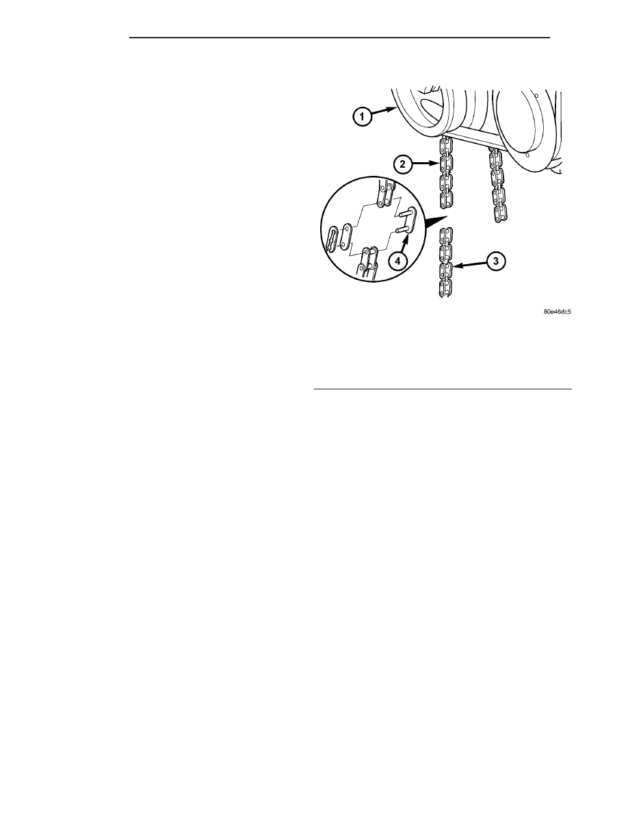
(1) Connect old oil pump chain and new chain with

temporary link, outer plate and locking element (Fig.
61).

(2) Slowly rotate crankshaft in a clockwise direc-

tion until it is possible to connect the ends of the new
and old oil pump chains.

(3) Remove assembly locking element, outer plate

and assembly link (Fig. 62).

Fig. 61 INSTALLING OIL PUMP CHAIN TEMPORARY

LINK

1 - VIBRATION DAMPER/CRANKSHAFT PULLEY
2 - OLD OIL PUMP CHAIN
3 - NEW OIL PUMP CHAIN
4 - TEMPORARY LINK

9 - 62

ENGINE

VA

CAUTION: Insert new riveted link from the rear.

(4) Connect ends of new oil pump chain with new

riveted link (Fig. 63).

NOTE: When assembling riveting tool, one piece is
secured by a screw and the other can move loosely
on the thrust spindle.

NOTE: The outer plate will be held in place by a
magnet.

(5) Place new outer plate into tool insert.

NOTE: Ensure that the riveted link and riveting tool
are aligned.

(6) Position riveting tool over new link and press

in new rivet as far as the tool stop.

(7) Remove riveting tool to change inserts.
(8) Install insert on riveting tool and secure with

screw.

(9) Install insert on riveting tool (Fig. 64).

NOTE: The outer plate is held in place magnetically
by riveting tool.

(10) Insert new outer plate into the moving assem-

bly insert.

(11) Position riveting tool so that spacer webs of

the guide are side by side.

(12) Ensure that riveted link and outer plate are

aligned.

NOTE: When turning spindle of riveting tool, be
sure that pins of riveted link are inserted into holes
of outer plate.

(13) Screw in spindle of riveting tool until firm

resistance is felt.

Fig. 62 REMOVING OIL PUMP CHAIN TEMPORARY

LINK

1 - NEW OIL PUMP CHAIN
2 - OLD OIL PUMP CHAIN
3 - TEMPORARY LINK

Fig. 63 INSTALLING NEW RIVETED LINK

1 - NEW RIVETED LINK
2 - OIL PUMP CHAIN

Fig. 64 INSTALLING RIVETING INSERTS INTO

RIVETING TOOL

1 - SPECIAL TOOL #9312-1
2 - SPECIAL TOOL #9312-5 and #9312-9

VA

ENGINE

9 - 63

(14) Remove riveting tool.
(15) Turn over tool moving assembly insert to the

riveting profile.

NOTE: Rivet pins of the riveted link individually.

(16) Position riveting tool exactly over middle of

pin (Fig. 65).

(17) Tighten riveting tool spindle until it stops.
(18) Remove riveting tool, inspect riveting, re-rivet

if necessary (Fig. 66).

(19) Repeat procedure for both rivets.

(20) Install oil pump (Refer to 9 - ENGINE/LU-

BRICATION/OIL PUMP - INSTALLATION).

(21) Install oil pan (Refer to 9 - ENGINE/LUBRI-

CATION/OIL PAN - INSTALLATION).

(22) Refill engine with proper oil to the correct

level (Refer to LUBRICATION & MAINTENANCE/
FLUID TYPES - SPECIFICATIONS).

(23) Connect negative battery cable.
(24) Start engine and inspect for leaks.

OIL SENSOR

DESCRIPTION

Oil level, oil temperature and oil quality are

detected by means of an oil sensor located in the oil
pan. The sensor which operates on the capacitance
principle features an integrated electronic circuit
which analyzes the three signals. the signals are con-
stantly relayed to the ECM and over the CAN bus to
the instrument cluster by means of PWM signal.

OPERATION

Oil quality is detected for indicating the need-

based oil change interval. The oil quality is detected
on the basis of the capacitance of the engine oil
(dielectrics, does not conduct electricity), this being
as much as six times greater in case of poor quality.

Oil level and oil quality are separate of each other.

The information is first of all compensated in the
ECM before being transmitted over the CAN bus.

Faults at the oil sensor are detected by the ECM

and entered into fault memory. The voltage for the
oil sensor (approx.5V) is supplied by the ECM.

Fig. 65 NEW LINK RIVETING

1 - SPECIAL TOOL #9312-5 INSERT
2 - SPECIAL TOOL #9312-1 RIVETING TOOL
3 - SPECIAL TOOL #9312-4 THRUST SPINDLE
4 - SPECIAL TOOL #9312-3 THRUST PIN
5 - SPECIAL TOOL #9312-12 INSERT
6 - OIL PUMP CHAIN

Fig. 66 RIVET INSPECTION

9 - 64

ENGINE

VA

REMOVAL

(1) Disconnect the negative battery cable.
(2) Raise and support the vehicle.
(3) Drain engine oil into a suitable, and appropri-

ately marked container.

(4) Remove engine mount to chassis nuts.
(5) Lower vehicle and install engine support.
(6) Remove the turbo charger heat shield to radia-

tor support bolts.

(7) Raise engine until the weight of the engine no

longer rests on the engine mounts.

(8) Raise and support the vehicle.
(9) Detach the front stabilizer bar at the front axle

and rotate it downward.

(10) Unplug the oil level sensor (Fig. 67).
(11) Remove the oil level sensor retaining screw,

oil level sensor and discard the O-ring (Fig. 67).

INSTALLATION

(1) Seat new O-ring on oil level sensor and lubri-

cate O-ring with clean engine oil (Fig. 67).

(2) Install the oil level sensor into the oil pan and

tighten screw to 124 lbs. in.(14N·m) (Fig. 67).

(3) Connect oil level sensor wiring harness connec-

tor (Fig. 67).

(4) Rotate front stabilizer bar upward and secure

to axle beam. Tighten to 22 lbs.ft. (30 N·m)

(5) Lower the vehicle.
(6) Lower the engine into the mounts.
(7) Remove engine support fixture.

(8) Raise and support the vehicle.
(9) Tighten both engine mount to chassis nuts.
(10) Install and tighten oil drain plug.
(11) Lower vehicle and install the appropriate

engine oil.

INTAKE MANIFOLD

REMOVAL

WARNING:

NO

FIRE,

SPARKS

OR

SMOKING.

STORE FUELS ONLY INTO SUITABLE AND APPRO-
PRIATELY

MARKED

CONTAINERS,

AND

WEAR

PROTECTIVE CLOTHING. (Refer to 14 - FUEL SYS-
TEM - WARNING).

WARNING: DO NOT OPEN THE COOLING SYSTEM
UNLESS THE COOLANT TEMPERATURE IS BELOW
90°C (194°F). OPEN RADIATOR CAP SLOWLY TO
RELEASE PRESSURE. STORE COOLANT ONLY
INTO SUITABLE AND APPROPRIATELY MARKED
CONTAINERS, WEAR PROTECTIVE CLOTHING AND
EYE PROTECTION.

(1) Disconnect the negative battery cable.
(2) Partially drain coolant from the radiator.
(3) Remove the engine cover (Refer to 9 - ENGINE

- REMOVAL).

(4) Remove the high pressure fuel lines (Fig. 68).

Fig. 67 OIL LEVEL SENSOR

1 - OIL PAN
2 - O-RING
3 - WIRING HARNESS
4 - BOLT
5 - OIL LEVEL SENSOR

VA

ENGINE

9 - 65


Content   ..  229  230  231  232   ..