Dodge Sprinter. Manual - part 223


  Index      Dodge     Dodge Sprinter / Mercedes-Benz - service repair manual 2006 year


Search            


Content   ..  221  222  223  224   ..


Dodge Sprinter. Manual - part 223


WARNING: USE EXTREME CAUTION WHEN THE
ENGINE IS OPERATING. DO NOT STAND IN A
DIRECT LINE WITH THE FAN. DO NOT PUT YOUR
HANDS NEAR THE PULLEYS, BELTS OR FAN. DO
NO WEAR LOOSE CLOTHING.

(11) Start the engine and inspect for leaks.

STANDARD PROCEDURE - INSPECTING TAP-
PET CLEARANCE

(1) Check engine oil level, adjust as necessary.
(2) Warm

engine

to

operating

temperature

(approx. 80°C, 176°F).

(3) Remove the cylinder head cover (Refer to 9 -

ENGINE/CYLINDER

HEAD/CYLINDER

HEAD

COVER(S) - REMOVAL).

(4) Rotate the engine by the crankshaft until the

camshaft, at the tappet to be tested, is at it’s base
circle (camshaft nose must point upward) (Fig. 20).

NOTE: Do not use a tool that will mar or damage
the tappet surface. If applied pressure is too strong
the tappet will appear to drop, but what happens is,
the valve opens.

(5) Use a pressing tool and apply pressure to the

tappet by hand (Fig. 20).

(6) If the tappet drops faster in comparison to the

other tappets, remove the camshaft and replace the
tappet.

REMOVAL

NOTE: Tappets are serviced Only when replacing
the camshaft housing. Inspect tappet clearance
(Refer

to

9

-

ENGINE/CYLINDER

HEAD/CAM-

SHAFT(S) - STANDARD PROCEDURE).

(1) Disconnect negative battery cable.
(2) Remove engine cover. (Refer to 9 - ENGINE -

REMOVAL).

WARNING: (Refer to 14 - FUEL SYSTEM - WARN-
ING)

(3) Remove

high

pressure

lines

and

injectors

(Refer to 14 - FUEL SYSTEM/FUEL INJECTION/
FUEL INJECTOR - REMOVAL).

(4) Remove cylinder head cover (Refer to 9 -

ENGINE/CYLINDER

HEAD/CYLINDER

HEAD

COVER(S) - REMOVAL).

NOTE: Rotate engine at the crankshaft only. DO
NOT rotate the engine at the camshaft. DO NOT
rotate the engine backward.

(5) Position piston of cylinder #1 to ignition TDC.
(6) Lock inlet camshaft (Fig. 21).

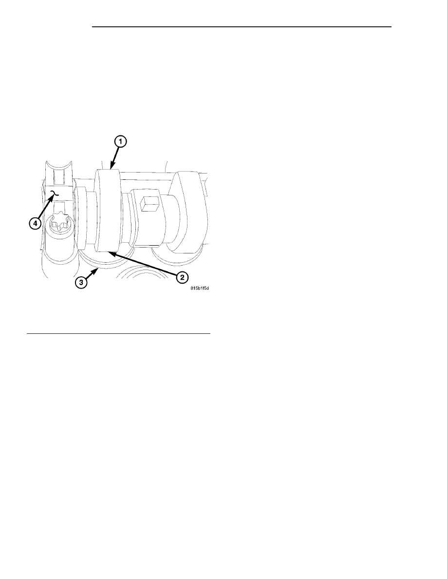
Fig. 20 TAPPET CLEARANCE

1 - CAMSHAFT
2 - PRESSURE APPLICATION POINT
3 - HYDRAULIC TAPPET
4 - CAMSHAFT HOLD DOWN

9 - 30

ENGINE

VA

(7) Remove timing chain tensioner (Refer to 9 -

ENGINE/VALVE

TIMING/TIMING

BELT/CHAIN

AND SPROCKETS - REMOVAL).

NOTE: The lower portion of the cylinder head front
cover is sealed with RTV sealant. Carefully tug front
cover after bolt removal to loosen from cylinder
head.

(8) Remove cylinder head front cover (Refer to 9 -

ENGINE/CYLINDER HEAD - REMOVAL).

(9) Remove top side rail (Refer to 9 - ENGINE/

CYLINDER HEAD - REMOVAL).

CAUTION: For all work in which the crankshaft
should not rotate, secure camshaft gear to timing
chain.

(10) Mark camshaft sprocket relative to timing

chain.

(11) Unbolt camshaft sprocket from exhaust cam-

shaft.

NOTE: Note the position of dowel pin for camshaft
sprocket alignment during reassembly.

(12) Remove camshaft sprocket.

CAUTION: Camshaft bearing caps must remain in
proper order and position.

NOTE: Slacken the bolts of the camshaft bearing
caps evenly in steps of one turn until the back
pressure is eliminated. Camshafts must not be
twisted when slackening the camshaft bearing
caps.

(13) Paint mark or scribe each camshaft bearing

cap, identifying which camshaft and which position.

(14) Remove the camshaft bearing caps at exhaust

camshaft bearing cap #1, #3,#4 and #6 in sequence.

(15) Remove the camshaft bearing caps at intake

camshaft bearing cap #1, #3,#4 and #6 in sequence.

(16) Slacken the exhaust camshaft bearing cap

bolts individually at the #2 cap then the #5 cap in
steps of one revolution until the back pressure is
removed.

(17) Slacken the intake camshaft bearing cap bolts

individually at the #2 cap then the #5 cap in steps of
one revolution until the back pressure is removed.

(18) Remove the inlet and exhaust camshafts (Fig.

22).

NOTE: Inspect camshaft and housing for wear or
damage. Inspect the housing oiling ducts for build
up or restrictions, clean as necessary. Also inspect
the camshaft end cover for wear or damage, replace
camshaft as necessary.

Fig. 21 CAMSHAFT ALIGNMENT

1 - EXHAUST CAMSHAFT SPROCKET AND CHAIN MARKING
2 - EXHAUST CAMSHAFT SPROCKET BOLTS
3 - EXHAUST CAMSHAFT SPROCKET
4 - CAMSHAFT ALIGNMENT DOTS
5 - INTAKE CAMSHAFT LOCK POSITION
6 - INTAKE CAMSHAFT SPROCKET
7 - INTAKE CAMSHAFT LOCK (SPECIAL TOOL #8929)
8 - INTAKE CAMSHAFT SPROCKET

VA

ENGINE

9 - 31

INSTALLATION

CAUTION: The camshafts are sensitive to fractur-
ing. Ensure they are installed free of stress. Oil
bucket

tappets

and

camshaft

bearing

points.

Inspect ease of operation of bucket tappets.

CAUTION: Pay attention to assignment of cam-
shafts. Camshaft code numbers are visible on the
thrust collar of the axial bearing. Install camshafts
so that the two holes in camshaft sprockets are
positioned opposite and the markings of the cam-
shaft and camshaft bearing cap are aligned.

(1) Install inlet and exhaust camshafts.

NOTE: Tappets are Only serviced when replacing
the camshaft housing. Inspect tappet clearence
(Refer

to

9

-

ENGINE/CYLINDER

HEAD/CAM-

SHAFT(S) - STANDARD PROCEDURE).

(2) Align inlet and exhaust camshafts at axial

bearing (Refer to 9 - ENGINE/CYLINDER HEAD/
CAMSHAFT(S) - STANDARD PROCEDURE).

NOTE: Pay attention to markings on camshaft bear-
ing caps.

CAUTION: Do not rotate engine counter clockwise.

(3) Position the piston of cylinder #1 to ignition

TDC.

NOTE: Pay attention to markings on camshaft bear-
ing caps and follow the tightening procedure below.

(4) Install the #2 and #5 Exhaust cam bearing

caps (Fig. 23).

(5) Install the #2 and #5 Intake cam bearing caps

(Fig. 23).

(6) Tighten each of the #2 and #5 Intake and

Exhaust bearing cap bolts evenly to 9N·m (80 lbs.
in.) in steps each of 1 revolution (Fig. 23).

(7) Install the remaining Intake and Exhaust cam

bearing caps and tighten them evenly to 9N·m (80
lbs. in.) in steps each of 1 revolution (Fig. 24).

Fig. 22 CAMSHAFTS AND HOUSING ASSEMBLY

1 - CYLINDER HEAD BOLTS
2 - EXHAUST CAMSHAFT
3 - INTAKE CAMSHAFT
4 - CAMSHAFT HOUSING
5 - CYLINDER HEAD

Fig. 23 CAMSHAFT BEARING TIGHTENING

SEQUENCE #1

9 - 32

ENGINE

VA

NOTE: The piston of cylinder #1 must be positioned
at ignition TDC when the inlet camshaft is locked.

(8) Insert locking pin through the first camshaft

bearing cap into the whole in the camshaft sprocket.

NOTE: Do Not use old camshaft sprocket bolts.

(9) Fit camshaft sprocket with timing chain fitted

on, onto exhaust camshaft paying attention to posi-
tion of dowel pin. Tighten bolt to 18N·m (159 lbs.in.).

(10) Install timing chain tensioner (Refer to 9 -

ENGINE/VALVE

TIMING/TIMING

BELT/CHAIN

AND SPROCKETS - INSTALLATION).

(11) Inspect/Set basic position of camshafts (Refer

to 9 - ENGINE/CYLINDER HEAD/CAMSHAFT(S) -
STANDARD PROCEDURE).

(12) Insert slide rail and bolt the driver into the

inlet camshaft. Tighten bolt driver to 50N·m (37 lbs.
in.).

(13) Install front cover at cylinder head.
(14) Install cylinder head cover (Refer to 9 -

ENGINE/CYLINDER

HEAD/CYLINDER

HEAD

COVER(S) - INSTALLATION).

NOTE: Refer to the appropriate injector servicing
procedures for cleaning of injectors and recesses.

(15) Clean and install injectors (Refer to 14 -

FUEL SYSTEM/FUEL INJECTION/FUEL INJEC-
TOR - STANDARD PROCEDURE), (Refer to 14 -
FUEL SYSTEM/FUEL INJECTION/FUEL INJEC-
TOR - INSTALLATION).

(16) Reconnect negative battery cable.

WARNING: (Refer to 14 - FUEL SYSTEM - WARN-
ING).

WARNING: USE EXTREME CAUTION WHEN THE
ENGINE IS OPERATING. DO NOT STAND IN A
DIRECT LINE WITH THE FAN. DO NOT PUT YOUR
HANDS NEAR THE PULLEYS, BELTS OR FAN. DO
NOT WEAR LOOSE CLOTHING.

(17) Start engine and inspect for leaks.Care must

be taken to observe the fuel system warning (Refer to
14 - FUEL SYSTEM - WARNING).

(18) Install engine cover (Refer to 9 - ENGINE

COVER - INSTALLATION).

CYLINDER HEAD COVER(S)

REMOVAL

(1) Disconnect negative battery cable.
(2) Disconnect the air inlet and set aside.
(3) Detach hose from oil separator.
(4) Disconnect the camshaft position sensor.
(5) Disconnect fuel injector and glow plug harness

and set aside.

(6) Remove fuel high pressure pipes and injectors

(Refer to 14 - FUEL SYSTEM/FUEL INJECTION/
FUEL INJECTOR - REMOVAL).

(7) Disconnect the out let line.
(8) Remove cylinder head cover retaining bolts and

remove cover (Fig. 25).

Fig. 24 CAMSHAFT BEARING TIGHTENING

SEQUENCE #2

VA

ENGINE

9 - 33


Content   ..  221  222  223  224   ..