Dodge Durango (HB). Manual - part 976


  Index      Dodge     Dodge Durango (HB) - service repair manual 2005 year


Search            


Content   ..  974  975  976  977   ..


Dodge Durango (HB). Manual - part 976


P2135-THROTTLE POSITION SENSOR 1/2 CORRELATION (CONTINUED)

7.

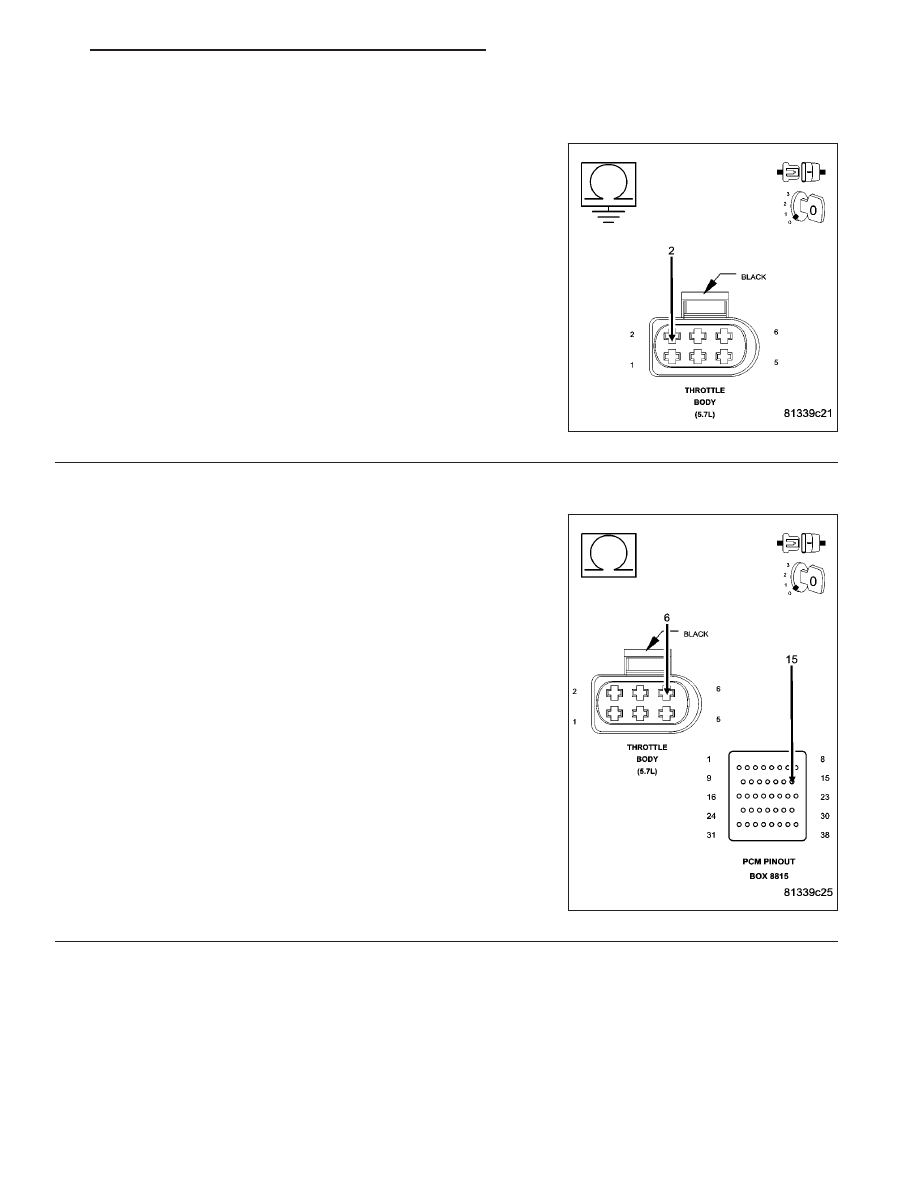
(F855) 5-VOLT SUPPLY SHORTED TO GROUND

Measure the resistance between ground and the (F855) 5-volt Supply
circuit at the appropriate terminals of special tool #8815.

Is the resistance below 100 ohms?

Yes

>> Repair the short to ground in the (F855) 5-volt Supply cir-

cuit.

Perform the POWERTRAIN VERIFICATION TEST. (Refer
to 9 - ENGINE - STANDARD PROCEDURE)

No

>> Go To 8

8.

EXCESSIVE RESISTANCE IN THE (K922) SENSOR RETURN CIRCUIT

CAUTION: Do not probe the PCM harness connectors. Probing
the PCM harness connectors will damage the PCM terminals
resulting in poor terminal to pin connection. Install Miller Special
Tool #8815 to perform diagnosis.
Measure the resistance of the (K922) Sensor Return circuit from the
Throttle Body harness connector to the appropriate terminal of special
tool #8815.

Is the resistance below 5.0 ohms?

Yes

>> Go To 9

No

>> Repair the excessive resistance in the (K922) Sensor

Return circuit.

Perform the POWERTRAIN VERIFICATION TEST. (Refer
to 9 - ENGINE - STANDARD PROCEDURE)

HB

ENGINE ELECTRICAL DIAGNOSTICS

9 - 903

P2135-THROTTLE POSITION SENSOR 1/2 CORRELATION (CONTINUED)

9.

(K22) TP SENSOR NO.1 SIGNAL SHORTED TO (K122) TP SENSOR NO.2 SIGNAL

Measure the resistance between the (K22) TP Sensor No.1 Signal cir-
cuit and the (K122) TP Sensor No.2 Signal circuit between the appro-
priate terminals of special tool #8815.

Is the resistance below 5.0 ohms?

Yes

>> Repair the short between the (K122) TP Sensor No.2 Sig-

nal circuit and the (K22) TP Sensor No.1 Signal circuit.

Perform the POWERTRAIN VERIFICATION TEST. (Refer
to 9 - ENGINE - STANDARD PROCEDURE)

No

>> Go To 10

10.

PCM

NOTE: Before continuing, check the PCM harness connector terminals for corrosion, damage, or terminal
push out. Repair as necessary.
Using the schematics as a guide, inspect the wire harness and connectors. Pay particular attention to all Power and
Ground circuits.

Were there any problems found?

Yes

>> Repair as necessary.

Perform the POWERTRAIN VERIFICATION TEST. (Refer to 9 - ENGINE - STANDARD PROCEDURE)

No

>> Replace and program the Powertrain Control Module per Service Information.

Perform the POWERTRAIN VERIFICATION TEST. (Refer to 9 - ENGINE - STANDARD PROCEDURE)

11.

THROTTLE FOLLOWER TEST

Ignition on, engine not running.

With a scan tool, perform the Throttle Follower Test and monitor the TP Sensor No.1 or No.2 voltage.

Slowly press the throttle pedal down.

The voltage for TP Sensor No.1 should start at approximately 0.8 of a volt and increase to above 4.2 volts.

The voltage for TP Sensor No.2 should start at approximately 4.2 volts and decrease to approximately 0.8 of a volt.

Is the voltage within the range of the listed specification for the appropriate Sensor?

Yes

>> Refer to the INTERMITTENT CONDITION Diagnostic Procedure.

Perform the POWERTRAIN VERIFICATION TEST. (Refer to 9 - ENGINE - STANDARD PROCEDURE)

No

>> Disconnect the Battery when replacing the Throttle Body Assembly. Replace the Throttle Body Assem-

bly. After installation is complete, use a scan tool and select the ETC RELEARN function.

Perform the POWERTRAIN VERIFICATION TEST. (Refer to 9 - ENGINE - STANDARD PROCEDURE)

9 - 904

ENGINE ELECTRICAL DIAGNOSTICS

HB

P2138-ACCELERATOR PEDAL POSITION SENSOR 1/2 CORRELATION

HB

ENGINE ELECTRICAL DIAGNOSTICS

9 - 905

P2138-ACCELERATOR PEDAL POSITION SENSOR 1/2 CORRELATION (CONTINUED)

For the Engine circuit diagram (Refer to 9 - ENGINE - SCHEMATICS AND DIAGRAMS).

For a complete wiring diagram Refer to Section 8W.

When Monitored:
With the ignition on and no APPS No.1 and APPS No.2 DTC present.

Set Condition:
APPS values No.1 and No.2 are not coherent. Idle is additionally forced when the brake pedal is pressed or
failed. Acceleration rate and Engine output are limited. One trip fault and the code will set within 5 seconds.
ETC light is flashing.

Possible Causes

EXCESSIVE RESISTANCE IN THE (F855) 5-VOLT SUPPLY CIRCUIT

EXCESSIVE RESISTANCE IN THE (F856) 5-VOLT SUPPLY CIRCUIT

EXCESSIVE RESISTANCE IN THE (K4) SENSOR NO.1 RETURN CIRCUIT

EXCESSIVE RESISTANCE IN THE (K400) SENSOR NO.2 RETURN CIRCUIT

EXCESSIVE RESISTANCE IN THE (K23) APP SENSOR NO.1 SIGNAL CIRCUIT

EXCESSIVE RESISTANCE IN THE (K29) APP SENSOR NO.2 SIGNAL CIRCUIT

APP SENSOR

PCM

Always perform the Pre-Diagnostic Troubleshooting procedure before proceeding. (Refer to 9 - ENGINE -
DIAGNOSIS AND TESTING).

Diagnostic Test

1.

ACTIVE DTC

Ignition on, engine not running.

With a scan tool, read DTCs.

NOTE: Repair any other 5-Volt Supply or APPS High and Low DTCs before diagnosing P2138.

Is the DTC active at this time?

Yes

>> Go To 2

No

>> Refer to the INTERMITTENT CONDITION Diagnostic Procedure.

Perform the POWERTRAIN VERIFICATION TEST. (Refer to 9 - ENGINE - STANDARD PROCEDURE)

9 - 906

ENGINE ELECTRICAL DIAGNOSTICS

HB


Content   ..  974  975  976  977   ..