Dodge Durango (HB). Manual - part 974
P2128-ACCELERATOR PEDAL POSITION SENSOR 2 CIRCUIT HIGH (CONTINUED)
5.
(K29) APPS NO.2 SIGNAL CIRCUIT SHORTED TO THE (F855) 5-VOLT SUPPLY CIRCUIT
Measure the resistance between the (K29) APP Sensor No.2 Signal
circuit and the (F855) 5-volt Supply circuit in the APP Sensor harness
connector.
Is the resistance below 10 ohms?
Yes
>> Repair the short between the (K29) APP Sensor No.2 Sig-
nal circuit and the (F855) 5-volt Supply circuit.
Perform the POWERTRAIN VERIFICATION TEST. (Refer
to 9 - ENGINE - STANDARD PROCEDURE)
No
>> Go To 6
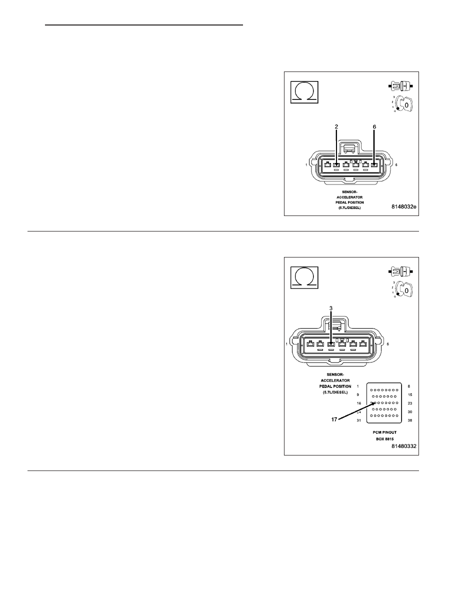
6.
(K400) APP SENSOR NO.2 RETURN CIRCUIT OPEN
CAUTION: Do not probe the PCM harness connectors. Probing
the PCM harness connectors will damage the PCM terminals
resulting in poor terminal to pin connection. Install Miller Special
Tool #8815 to perform diagnosis.
Measure the resistance of the (K400) APP Sensor No.2 Return circuit
from the APP Sensor harness connector to the appropriate terminal of
special tool #8815.
Is the resistance below 5.0 ohms?
Yes
>> Go To 7
No
>> Repair the open in the (K400) APP Sensor No.2 Return
circuit.
Perform the POWERTRAIN VERIFICATION TEST. (Refer
to 9 - ENGINE - STANDARD PROCEDURE)
HB
ENGINE ELECTRICAL DIAGNOSTICS
9 - 895