Dodge Durango (HB). Manual - part 972
P2127-ACCELERATOR PEDAL POSITION SENSOR 2 CIRCUIT LOW (CONTINUED)
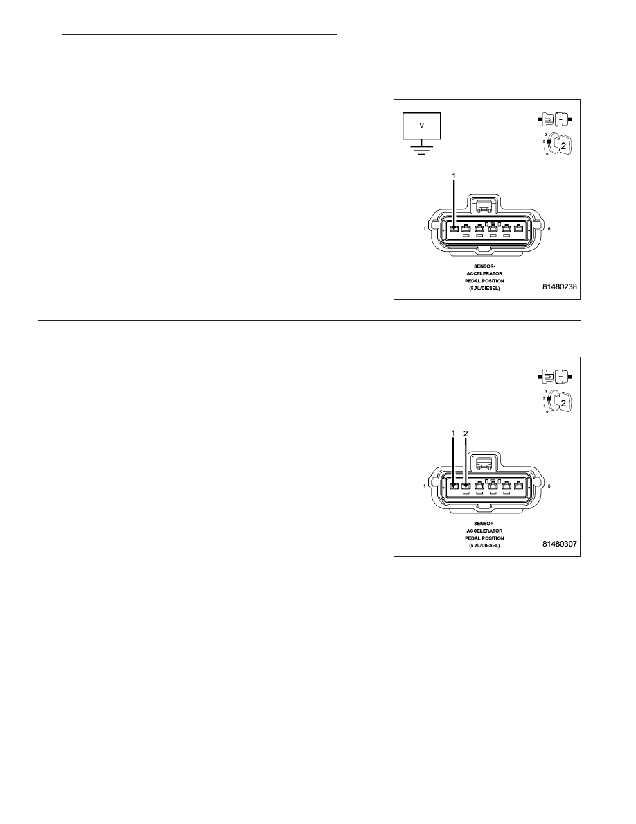
2.
(F856) 5-VOLT SUPPLY CIRCUIT
Turn the ignition off.
Disconnect the APP Sensor harness connector.
Ignition on, engine not running.
Measure the voltage on the (F856) 5-volt Supply circuit in the APP
Sensor harness connector.
Is the voltage between 4.5 and 5.2 volts?
Yes
>> Go To 3
No
>> Go To 8
3.
ACCELERATOR PEDAL POSITION SENSOR
Connect a jumper wire between the (F856) 5-volt Supply circuit and
the (K29) APP Sensor No.2 Signal circuit in the Sensor harness con-
nector.
With a scan tool, monitor the APP Sensor No.2 voltage.
Is the voltage above 4.5 volts with the jumper wire installed?
Yes
>> Replace the APP Sensor Assembly per Service Informa-
tion. After installation is complete, use a scan tool and
select the ETC RELEARN function to relearn the APPS
values.
Perform the POWERTRAIN VERIFICATION TEST. (Refer
to 9 - ENGINE - STANDARD PROCEDURE)
No
>> Go To 4
NOTE: Remove the jumper wire before continuing.
HB
ENGINE ELECTRICAL DIAGNOSTICS
9 - 887