Dodge Durango (HB). Manual - part 970


  Index      Dodge     Dodge Durango (HB) - service repair manual 2005 year


Search            


Content   ..  968  969  970  971   ..


Dodge Durango (HB). Manual - part 970


P2122-ACCELERATOR PEDAL POSITION SENSOR 1 CIRCUIT LOW (CONTINUED)
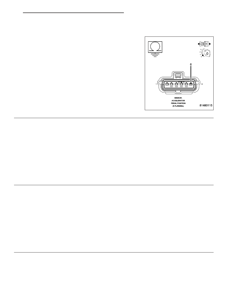
9.

(F855) 5-VOLT SUPPLY CIRCUIT SHORTED TO GROUND

Measure the resistance between ground and the (F855) 5-volt Supply
circuit in the APP Sensor harness connector.

Is the resistance below 100 ohms?

Yes

>> Repair the short to ground in the (F855) 5-volt Supply cir-

cuit.

Perform the POWERTRAIN VERIFICATION TEST. (Refer
to 9 - ENGINE - STANDARD PROCEDURE)

No

>> Go To 10

10.

PCM

NOTE: Before continuing, check the PCM harness connector terminals for corrosion, damage, or terminal
push out. Repair as necessary.
Using the schematics as a guide, inspect the wire harness and connectors. Pay particular attention to all Power and
Ground circuits.

Were there any problems found?

Yes

>> Repair as necessary.

Perform the POWERTRAIN VERIFICATION TEST. (Refer to 9 - ENGINE - STANDARD PROCEDURE)

No

>> Replace and program the Powertrain Control Module per Service Information.

Perform the POWERTRAIN VERIFICATION TEST. (Refer to 9 - ENGINE - STANDARD PROCEDURE)

11.

APP SENSOR SWEEP

Ignition on, engine not running.

With a scan tool, monitor the APP Sensor No.1 voltage.

Slowly press the Accelerator pedal down.

Does voltage start at approximately 0.45 of a volt and go above 4.6 volts with a smooth transition?

Yes

>> Refer to the INTERMITTENT CONDITION Diagnostic Procedure.

Perform the POWERTRAIN VERIFICATION TEST. (Refer to 9 - ENGINE - STANDARD PROCEDURE)

No

>> Replace the APP Sensor Assembly per Service Information. After installation is complete, use a scan

tool and select the ETC RELEARN function to relearn the APPS values.

Perform the POWERTRAIN VERIFICATION TEST. (Refer to 9 - ENGINE - STANDARD PROCEDURE)

HB

ENGINE ELECTRICAL DIAGNOSTICS

9 - 879

P2123-ACCELERATOR PEDAL POSITION SENSOR 1 CIRCUIT HIGH

9 - 880

ENGINE ELECTRICAL DIAGNOSTICS

HB

P2123-ACCELERATOR PEDAL POSITION SENSOR 1 CIRCUIT HIGH (CONTINUED)

For the Engine circuit diagram (Refer to 9 - ENGINE - SCHEMATICS AND DIAGRAMS).

For a complete wiring diagram Refer to Section 8W.

When Monitored:
With the ignition on and no other APPS No.1 DTCs present.

Set Condition:
When APP Sensor No.1 voltage is too high. Engine will additionally idle if the brake pedal is pressed or has
failed. Acceleration rate and Engine output are limited. One trip fault and the code will set within 5 seconds.
ETC light is flashing.

Possible Causes

(K23) APP SENSOR NO.1 SIGNAL CIRCUIT SHORTED TO BATTERY VOLTAGE

(K23) APP SENSOR NO.1 SIGNAL SHORTED TO THE (F855) 5-VOLT SUPPLY CIRCUIT

(K23) APP SENSOR NO.1 SIGNAL SHORTED TO THE (F856) 5-VOLT SUPPLY CIRCUIT

(K4) APP SENSOR NO.1 RETURN CIRCUIT OPEN

APP SENSOR

PCM

Always perform the Pre-Diagnostic Troubleshooting procedure before proceeding. (Refer to 9 - ENGINE -
DIAGNOSIS AND TESTING).

Diagnostic Test

1.

APPS NO.1 VOLTAGE ABOVE 4.8 VOLTS

Ignition on, engine not running.

With a scan tool, read the APP Sensor No.1 voltage.

Is the voltage above 4.8 volts?

Yes

>> Go To 2

No

>> Go To 8

2.

ACCELERATOR PEDAL POSITION SENSOR

Turn the ignition off.

Disconnect the APP Sensor harness connector.

Ignition on, engine not running.

With a scan tool, monitor the Accelerator Pedal Position Sensor voltage.

Is the voltage between 4.5 and 5.2 volts?

Yes

>> Go To 3

No

>> Replace the APP Sensor Assembly per Service Information. After installation is complete, use a scan

tool and select the ETC RELEARN function to relearn the APPS values.

Perform the POWERTRAIN VERIFICATION TEST. (Refer to 9 - ENGINE - STANDARD PROCEDURE)

HB

ENGINE ELECTRICAL DIAGNOSTICS

9 - 881

P2123-ACCELERATOR PEDAL POSITION SENSOR 1 CIRCUIT HIGH (CONTINUED)

3.

(K23) APP SENSOR NO.1 SIGNAL CIRCUIT SHORTED TO BATTERY VOLTAGE

Turn the ignition off.

Disconnect the C1, C2, and C3 PCM harness connectors.

Ignition on, engine not running.

Measure the voltage on the (K23) APP Sensor No.1 Signal circuit in
the APP Sensor harness connector.

Is the voltage above 0 volts?

Yes

>> Repair the short to battery voltage in the (K23) APP Sen-

sor No.1 Signal circuit.

Perform the POWERTRAIN VERIFICATION TEST. (Refer
to 9 - ENGINE - STANDARD PROCEDURE)

No

>> Go To 4

4.

(K23) APPS NO.1 SIGNAL CIRCUIT SHORTED TO THE (F855) 5-VOLT SUPPLY CIRCUIT

Turn the ignition off.

Measure the resistance between the (K23) APP Sensor No.1 Signal
circuit and the (F855) 5-volt Supply circuit in the APP Sensor harness
connector.

Is the resistance below 100 ohms?

Yes

>> Repair the short between the (K23) APP Sensor No.1 Sig-

nal circuit and the (F855) 5-volt Supply circuit.

Perform the POWERTRAIN VERIFICATION TEST. (Refer
to 9 - ENGINE - STANDARD PROCEDURE)

No

>> Go To 5

9 - 882

ENGINE ELECTRICAL DIAGNOSTICS

HB


Content   ..  968  969  970  971   ..