Dodge Durango (HB). Manual - part 919
P0594-SPEED CONTROL SERVO POWER RELAY CIRCUIT (CONTINUED)
3.
STOP LAMP SWITCH
Disconnect and remove the Stop Lamp Switch.
Measure the resistance across the (V32) S/C Supply circuit terminal and the (V30) S/C Brake Switch Output circuit
terminal in the Stop Lamp Switch.
Push the Plunger of the Switch in and let it out.
Does the resistance change from below 5.0 ohms to an open circuit?
Yes
>> Go To 4
No
>> Replace the Stop Lamp Switch.
Perform the POWERTRAIN VERIFICATION TEST. (Refer to 9 - ENGINE - STANDARD PROCEDURE)
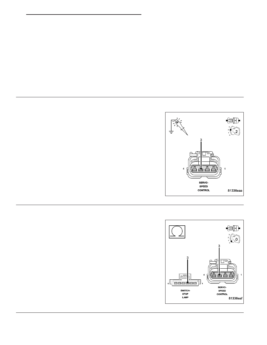
4.
(V30) S/C BRAKE SWITCH OUTPUT
Turn the ignition off.
Connect the Stop Lamp Switch harness connector and install the
Switch.
Disconnect the Speed Control Servo harness connector.
Ignition on, engine not running.
NOTE: It is necessary to PRESS and HOLD the Speed Control
Switch in the ON position while checking for voltage.
Using a 12-volt test light connected to ground, probe the (V30) S/C
Brake Switch Output circuit in the Servo Harness connector.
Does the test light illuminate brightly?
Yes
>> Replace the S/C Servo.
Perform the POWERTRAIN VERIFICATION TEST. (Refer
to 9 - ENGINE - STANDARD PROCEDURE)
No
>> Go To 5
5.
(V30) S/C BRAKE SWITCH OUTPUT CIRCUIT OPEN
Turn the ignition off.
Disconnect the Brake Lamp Switch harness connector.
Measure the resistance of the (V30) S/C Brake Switch Output circuit
from the Stop Lamp Switch harness connector to the S/C Servo har-
ness connector.
Is the resistance below 5.0 ohms?
Yes
>> Repair the excessive resistance in the (V30) S/C Brake
Switch Output circuit.
Perform the POWERTRAIN VERIFICATION TEST. (Refer
to 9 - ENGINE - STANDARD PROCEDURE)
No
>> Go To 6
HB
ENGINE ELECTRICAL DIAGNOSTICS
9 - 675