Dodge Durango (HB). Manual - part 605


  Index      Dodge     Dodge Durango (HB) - service repair manual 2005 year


Search            


Content   ..  603  604  605  606   ..


Dodge Durango (HB). Manual - part 605


The wiper element flexor provides the claws of the blade superstructure with a rigid, yet flexible component on the
element which can be gripped. The rubber element is designed to be stiff enough to maintain an even cleaning
edge as it is drawn across the glass, yet resilient enough to conform to the glass surface and flip from one cleaning
edge to the other each time the wiper blade changes directions.

REMOVAL

CAUTION: Do not allow the wiper arm to spring back against the glass without the wiper blade in place or
the glass may be damaged.

NOTE: The notched end of the wiper element
flexor should always be oriented towards the end
of the wiper blade that is nearest to the wiper
pivot.

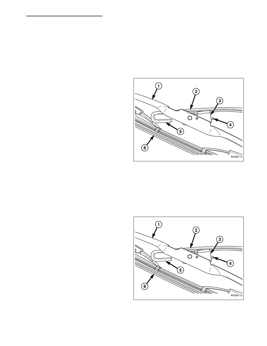
1. Lift the wiper arm (2) to raise the wiper blade and

element (6) off of the glass, until the wiper arm
hinge is in its over-center position.

2. To remove the blade from the arm, depress the

latch release tab (4) on the pivot block (3) under
the tip of the arm and slide the blade away from
the tip towards the pivot end of the arm far enough
to disengage the pivot block from the hook forma-
tion (5) on the end of the arm.

3. Extract the hook formation on the tip of the wiper

arm through the opening in the wiper blade super-
structure (1) just ahead of the pivot block.

4. Gently lower the tip of the wiper arm onto the glass.

INSTALLATION

CAUTION: Do not allow the wiper arm to spring back against the glass without the wiper blade in place or
the glass may be damaged.

NOTE: The notched end of the wiper element
flexor should always be oriented towards the end
of the wiper blade that is nearest to the wiper
pivot.

1. Lift the wiper arm (2) off of the windshield glass,

until the wiper arm hinge is in its over-center posi-
tion.

2. Position the wiper blade near the hook formation

(5) on the tip of the arm with the notched end of
the wiper element flexor oriented towards the end
of the wiper arm that is nearest to the wiper pivot.

3. Insert the hook formation on the tip of the arm

through the opening in the blade superstructure (1)
ahead of the pivot block (3) far enough to engage
the pivot block into the hook.

4. Slide the pivot block up into the hook formation on the tip of the wiper arm until the latch release tab (4) snaps

into its locked position. Latch engagement will be accompanied by an audible click.

5. Gently lower the wiper blade and element (6) onto the glass.

HB

FRONT WIPERS/WASHERS - SERVICE INFORMATION

8R - 43

HOSE-WINDSHIELD WASHER

DESCRIPTION

The front washer plumbing consists of a small diame-
ter rubber hose (4) that is routed along with the rear
washer hose (3) from the washer reservoir (6) under
the left front fender (2) ahead of the left front wheel to
the engine compartment. Both hoses are attached to
their respective front or rear outlet nipple of the
washer pump/motor unit (5) near the bottom of the
reservoir. The hoses are then secured by retainers to
the back of the condenser shroud and the underside
of the Power Distribution Center (PDC) bracket (1)
above the wheel house splash shield before entering
the left side of the engine compartment behind the
PDC.

In the engine compartment, both hoses are secured
by a retainer near the dash panel to the side support
member for the left front fender (5). The two hoses are
routed separately from this point. The front hose (4) is
routed up toward the hood (3), while the rear hose (6)
is routed through a grommet and a hole in the dash
panel into the passenger compartment.

The front hose is engaged in a molded retainer inte-
gral to the right end of the cowl plenum cover/grille
panel and is secured by a retainer near the hood
hinge bracket on the fender ledge. Two retainers
secure the hose to the underside of the hood panel
reinforcement. A molded plastic tee fitting with a short
connector hose provides the take out for the left
washer nozzle (2), and a plastic in-line fitting with a
rubber elbow terminate and connect the front hose at
the left washer nozzle (1).

Washer hose is available for service only as roll stock,
which must then be cut to length. The molded plastic
washer hose fittings cannot be repaired. If these fittings are faulty or damaged, they must be replaced.

OPERATION

Washer fluid in the washer reservoir is pressurized and fed by the windshield washer pump through the front washer
system plumbing and fittings to the two front washer nozzles. Whenever routing the washer hose or a wire harness

8R - 44

FRONT WIPERS/WASHERS - SERVICE INFORMATION

HB

containing a washer hose, it must be routed away from hot, sharp, or moving parts; and, sharp bends that might
pinch the hose must be avoided.

MODULE-WINDSHIELD WIPER

DESCRIPTION

The front wiper module is secured with screws through four rubber grommet-type insulators (4) to the cowl plenum
panel and the left front fender ledge. The module is located in the rear of the engine compartment where it is con-
cealed beneath the molded plastic cowl plenum cover/grille panel between the base of the windshield and the rear
edge of the hood panel. The ends of the pivot shafts protruding through openings in the cowl plenum cover/grille
panel are the only visible components of the wiper module. The wiper module consists of the following major com-
ponents:

Bracket (5) - The wiper module bracket is a single die cast aluminum unit that includes provisions for mount-
ing the wiper motor and wiper pivots as well as for the for rubber insulators used in mounting the bracket to
the vehicle.

Crank Arm (6) - The wiper motor crank arm is a stamped steel unit with an internally splined hole on the
driven end that is secured to the wiper motor output shaft with a nut, and a long ball stud secured to the drive
end to accept the wiper linkage.

Linkage (3) - The two wiper linkage members are each constructed of stamped steel. A driver side drive link
with a plastic socket-type bushing in the left end, and a plastic sleeve-type bushing in the right end. The socket
bushing is snap-fit over the pivot ball stud on the left pivot lever arm, while the sleeve bushing is fit over the
longer pivot stud on the wiper motor crank arm. The passenger side drive link has a plastic socket-type bush-
ing on each end. One end of this drive link is snap-fit over the ball stud on the right pivot lever arm, while the
other end is snap-fit over the top of the driver side drive link on the ball stud of the wiper motor crank arm.

Motor (7) - The wiper motor is secured on the underside of the module bracket near the center with three
screws. The wiper motor output shaft passes through a hole in the module bracket, where a nut secures the
wiper motor crank arm to the motor output shaft. The two-speed permanent magnet wiper motor features an
integral transmission, an internal park switch, and an internal Positive Temperature Coefficient (PTC) circuit
breaker.

Pivots (1 & 2) - This module features two driven pivots (2) and one drone pivot (1) for the articulating link of
the right wiper arm. The two driven wiper pivot shafts have lever arms with ball studs at their base to accept
the wiper linkage. The upper end of all three pivot shafts has a threaded stud with a tapered and serrated area
just below the threads to accept the left wiper arm or the right wiper arm links.

HB

FRONT WIPERS/WASHERS - SERVICE INFORMATION

8R - 45

The front wiper module cannot be adjusted or repaired. The front wiper motor is available for separate service
replacement. If any other component of the module is faulty or damaged, the entire front wiper module unit must be
replaced.

OPERATION

The front wiper module operation is controlled by the battery current inputs received by the wiper motor through the
wiper on/off and wiper high/low relays. The wiper motor speed is controlled by current flow to either the low speed
or the high speed set of brushes. The park switch is a single pole, single throw, momentary switch within the wiper
motor that is mechanically actuated by the wiper motor transmission components. The park switch alternately opens
and closes the wiper park switch sense circuit to ground, depending upon the position of the wipers on the glass.
This feature allows the motor to complete its current wipe cycle after the wiper system has been turned Off, and to
park the wiper blades in the lowest portion of the wipe pattern. The automatic resetting circuit breaker protects the
motor from overloads.

The wiper motor crank arm, the two wiper linkage members, and the two driven wiper pivots mechanically convert
the rotary output of the wiper motor to the back and forth wiping motion of the wiper arms and blades on the glass.
The drone pivot provides an anchor point for the articulating link of the right wiper arm.

REMOVAL

NOTE: The front wiper motor can be removed from the wiper module without removing the module from the
vehicle, and is available as a separate service component for this model. (Refer to 8 - ELECTRICAL/FRONT
WIPERS/WASHERS/FRONT WIPER MOTOR - REMOVAL).

1. Disconnect and isolate the battery negative cable.

2. Remove both front wiper arms from the wiper pivots. (Refer to 8 - ELECTRICAL/FRONT WIPERS/WASHERS/

FRONT WIPER ARMS - REMOVAL).

3. Remove the cowl plenum cover/grille panel from over the front wiper module. (Refer to 23 - BODY/EXTERIOR/

COWL GRILLE AND SCREEN - REMOVAL).

4. Disconnect the wire harness connector (5) from the front wiper motor connector.

5. Remove the screw (3) that secures the front wiper module bracket (6) and the center bracket of the cowl grille

support (7) to the cowl plenum panel (1).

8R - 46

FRONT WIPERS/WASHERS - SERVICE INFORMATION

HB


Content   ..  603  604  605  606   ..