Dodge Durango (HB). Manual - part 593


  Index      Dodge     Dodge Durango (HB) - service repair manual 2005 year


Search            


Content   ..  591  592  593  594   ..


Dodge Durango (HB). Manual - part 593


Each of these steps must be repeated and completed in their entirety for each additional Sentry Key that is to be
programmed. If the above steps are not completed in the given sequence, or within the allotted time, the SKREEM
will exit the Customer Learn programming mode and the programming will be unsuccessful. The SKREEM will also
automatically exit the Customer Learn programming mode if it sees a non-blank Sentry Key transponder when it
should see a blank, if it has already programmed eight (8) valid Sentry Keys, or if the ignition switch is turned to the
Off position for more than about fifty seconds.

NOTE: If an attempt is made to start the vehicle while in the Customer Learn mode (security indicator flash-
ing), the SKIS will respond as though the vehicle were being started with an invalid key. In other words, the
engine will stall after about two seconds of operation. No faults will be set.

NOTE: Once a Sentry Key has been programmed as a valid key to a vehicle, it cannot be programmed as a
valid key for use on any other vehicle.

TRANSPONDER KEY

DESCRIPTION

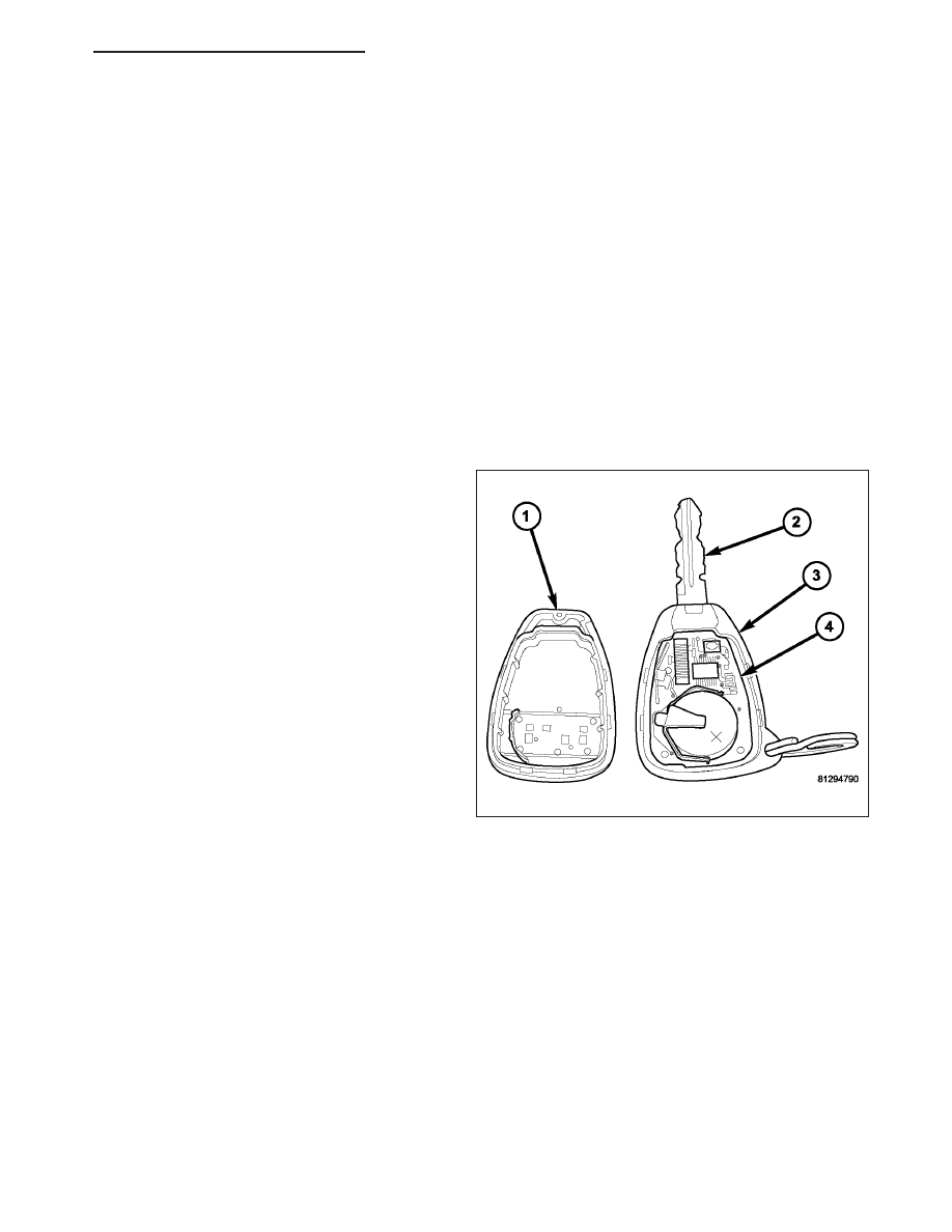
Each ignition key (2) used in the Sentry Key Immobi-
lizer System (SKIS) has a transponder chip included
on the circuit board (4) beneath the cover (1) of the
integral Remote Keyless Entry (RKE) transmitter (3).
In addition to having to be cut to match the mechani-
cal coding of the ignition lock cylinder and pro-
grammed for operation of the RKE system, each new
Sentry Key has a unique transponder identification
code that is permanently programmed into it by the
manufacturer, and which must be programmed into
the Sentry Key REmote Entry Module (SKREEM) to
be recognized by the SKIS as a valid key. The Sentry
Key transponder cannot be adjusted or repaired. If
faulty or damaged, the entire key and RKE transmitter
unit must be replaced.

OPERATION

When the ignition switch is turned to the On position, the Sentry Key REmote Entry Module (SKREEM) communi-
cates through its antenna with the Sentry Key transponder using a Radio Frequency (RF) signal. The SKREEM then
listens for a RF response from the transponder through the same antenna. The Sentry Key transponder chip is
within the range of the SKREEM transceiver antenna ring when it is inserted into the ignition lock cylinder. The
SKREEM determines whether a valid key is present in the ignition lock cylinder based upon the response from the
transponder. If a valid key is detected, that fact is communicated by the SKREEM to the Powertrain Control Module
(PCM) over the Controller Area Network (CAN) data bus, and the PCM allows the engine to continue running. If the
PCM receives an invalid key message, or receives no message from the SKREEM over the CAN data bus, the
engine will be disabled after about two seconds of operation. The ElectroMechanical Instrument Cluster (EMIC) will
also respond to the invalid key message on the CAN data bus by flashing the security indicator on and off.

Each Sentry Key has a unique transponder identification code permanently programmed into it by the manufacturer.
Likewise, the SKREEM has a unique Secret Key code programmed into it by the manufacturer. When a Sentry Key
is programmed into the memory of the SKREEM, the SKREEM stores the transponder identification code from the
Sentry Key, and the Sentry Key learns the Secret Key code from the SKREEM. Once the Sentry Key learns the
Secret Key code of the SKREEM, it is permanently stored in the memory of the transponder. Therefore, once a
Sentry Key has been programmed to a particular vehicle, it cannot be used on any other vehicle. (Refer to 8 -
ELECTRICAL/VEHICLE THEFT SECURITY - STANDARD PROCEDURE - TRANSPONDER PROGRAMMING).

HB

VEHICLE THEFT SECURITY - SERVICE INFORMATION

8Q - 91

The SKIS performs a self-test each time the ignition switch is turned to the On position, and will store key-related
fault information in the form of a Diagnostic Trouble Code (DTC) in SKREEM memory if a Sentry Key transponder
problem is detected. The Sentry Key transponder chip can be diagnosed, and any stored DTC can be retrieved
using a diagnostic scan tool. Refer to the appropriate diagnostic information.

MODULE-SENTRY KEY REMOTE ENTRY

DESCRIPTION

The Sentry Key REmote Entry Module (SKREEM) (1)
is sometimes referred to as the Wireless Control Mod-
ule (WCM). The SKREEM is the primary component of
the Sentry Key Immobilizer System (SKIS) and is also
the receiver for the Remote Keyless Entry (RKE) sys-
tem. The SKREEM is located on the right side of the
steering column, near the ignition lock cylinder hous-
ing and is concealed beneath the steering column
shrouds. The molded black plastic housing for the
SKREEM has an integral molded plastic halo-like
antenna ring (4) that extends from the bottom. When
the SKREEM is properly installed on the steering col-
umn, the antenna ring is oriented around the circum-
ference of the ignition lock cylinder housing.

A single integral connector receptacle (3) is located
just behind the antenna ring on the bottom of the
SKREEM housing. An integral molded plastic mount-
ing tab (2) on the rear corner of the SKREEM housing
has a hole in the center through which a screw
passes to secure the unit to the steering column. The
SKREEM is connected to the vehicle electrical system through a single take out and connector of the instrument
panel wire harness.

Two SKREEM modules are used: one for vehicles equipped with RKE only, and one for vehicles equipped with RKE
and SKIS. The SKREEM cannot be adjusted or repaired. If faulty or damaged, the entire SKREEM unit must be
replaced.

OPERATION

The Sentry Key REmote Entry Module (SKREEM) contains a Radio Frequency (RF) transceiver and a micropro-
cessor. The SKREEM transmits RF signals to, and receives RF signals from the Sentry Key transponder through a
tuned antenna enclosed within the molded plastic antenna ring integral to the SKREEM housing. If this antenna ring
is not mounted properly around the ignition lock cylinder housing, communication problems between the SKREEM
and the transponder may arise. These communication problems will result in Sentry Key transponder-related faults.
The SKREEM also serves as the Remote Keyless Entry (RKE) RF receiver. (Refer to 8 - ELECTRICAL/POWER
LOCKS - DESCRIPTION). The SKREEM communicates over the Controller Area Network (CAN) data bus with the
ElectroMechanical Instrument Cluster (EMIC), the Powertrain Control Module (PCM), and/or the diagnostic scan
tool.

The SKREEM retains in memory the ID numbers of any Sentry Key transponder that is programmed into it. A max-
imum of eight Sentry Key transponders can be programmed into the SKREEM. For added system security, each
SKREEM is programmed with a unique Secret Key code. This code is stored in memory, sent over the CAN data
bus to the PCM, and is encoded to the transponder of every Sentry Key that is programmed into the SKREEM.
Therefore, the Secret Key code is a common element that is found in every component of the Sentry Key Immo-
bilizer System (SKIS). Another security code, called a PIN, is used to gain access to the SKREEM Secured Access
Mode. The Secured Access Mode is required during service to perform the SKIS initialization and Sentry Key tran-
sponder programming procedures. The SKREEM also stores the Vehicle Identification Number (VIN) in its memory,
which it learns through a CAN data bus message from the PCM during SKIS initialization.

8Q - 92

VEHICLE THEFT SECURITY - SERVICE INFORMATION

HB

In the event that a SKREEM replacement is required, the Secret Key code can be transferred to the new SKREEM
from the PCM using the diagnostic scan tool and the SKIS initialization procedure. Proper completion of the SKIS
initialization will allow the existing Sentry Keys to be programmed into the new SKREEM so that new keys will not
be required. In the event that the original Secret Key code cannot be recovered, SKREEM replacement will also
require new Sentry Keys. The diagnostic scan tool will alert the technician during the SKIS initialization procedure if
new Sentry Keys are required.

When the ignition switch is turned to the On position, the SKREEM transmits an RF signal to the transponder in the
ignition key. The SKREEM then waits for an RF signal response from the transponder. If the response received
identifies the key as valid, the SKREEM sends a valid key message to the PCM over the CAN data bus. If the
response received identifies the key as invalid or if no response is received from the key transponder, the SKREEM
sends an invalid key message to the PCM. The PCM will enable or disable engine operation based upon the status
of the SKREEM messages. It is important to note that the default condition in the PCM is an invalid key; therefore,
if no message is received from the SKREEM by the PCM, the engine will be disabled and the vehicle immobilized
after two seconds of running.

The SKREEM also sends security indicator status messages to the EMIC over the CAN data bus to tell the EMIC
how to operate the security indicator. The security indicator status message from the SKREEM tells the EMIC to
turn the indicator on for about three seconds each time the ignition switch is turned to the On position as a bulb
test. After completion of the bulb test, the SKREEM sends security indicator status messages to the EMIC to turn
the indicator off, turn the indicator on, or to flash the indicator on and off. If the security indicator flashes or stays on
solid after the bulb test, it signifies a SKIS fault. If the SKREEM detects a system malfunction and/or the SKIS has
become inoperative, the security indicator will stay on solid. If the SKREEM detects an invalid key or if a key tran-
sponder-related fault exists, the security indicator will flash. If the vehicle is equipped with the Customer Learn tran-
sponder programming feature, the SKREEM will also send messages to the EMIC to flash the security indicator
whenever the Customer Learn programming mode is being utilized. (Refer to 8 - ELECTRICAL/VEHICLE THEFT
SECURITY - STANDARD PROCEDURE - SENTRY KEY TRANSPONDER PROGRAMMING).

The SKIS performs a self-test each time the ignition switch is turned to the On position, and will store fault infor-
mation in the form of a Diagnostic Trouble Code (DTC) in SKREEM memory if a system malfunction is detected.
The SKREEM can be diagnosed, and any stored DTC can be retrieved using a diagnostic scan tool. Refer to the
appropriate diagnostic information.

REMOVAL

WARNING: To avoid personal injury or death, on vehicles equipped with airbags, disable the supplemental
restraint system before attempting any steering wheel, steering column, airbag, occupant classification sys-
tem, seat belt tensioner, impact sensor, or instrument panel component diagnosis or service. Disconnect
and isolate the battery negative (ground) cable, then wait two minutes for the system capacitor to discharge
before performing further diagnosis or service. This is the only sure way to disable the supplemental
restraint system. Failure to take the proper precautions could result in accidental airbag deployment.

1. Disconnect and isolate the battery negative cable.

2. Grasp the tilt steering column knob firmly and pull it

straight rearward to remove it from the tilt adjuster
lever on the left side of the column.

3. From below the steering column, remove the two

outboard screws that secure the upper column
shroud (1) to the lower shroud (3).

4. Using hand pressure, push gently inward on both

sides of the upper shroud above the parting line of
the lower shroud to release the snap features that
secure the two shroud halves to each other.

5. Remove the upper shroud from the lower shroud

and the steering column.

6. Remove the one center screw that secures the

lower shroud to the steering column (4).

HB

VEHICLE THEFT SECURITY - SERVICE INFORMATION

8Q - 93

7. Remove the lower shroud from the steering column.

8. Disconnect the wire harness connector (2) from the

Sentry Key REmote Entry Module (SKREEM) (1).

9. Remove the screw (2) that secures the SKREEM

(1) to the steering column housing.

10. Disengage the antenna ring (4) from around the

ignition lock cylinder housing (3) and remove the
SKREEM.

INSTALLATION

WARNING: To avoid personal injury or death, on vehicles equipped with airbags, disable the supplemental
restraint system before attempting any steering wheel, steering column, airbag, occupant classification sys-
tem, seat belt tensioner, impact sensor, or instrument panel component diagnosis or service. Disconnect
and isolate the battery negative (ground) cable, then wait two minutes for the system capacitor to discharge
before performing further diagnosis or service. This is the only sure way to disable the supplemental
restraint system. Failure to take the proper precautions could result in accidental airbag deployment.

8Q - 94

VEHICLE THEFT SECURITY - SERVICE INFORMATION

HB


Content   ..  591  592  593  594   ..