Dodge Durango (HB). Manual - part 415
2.
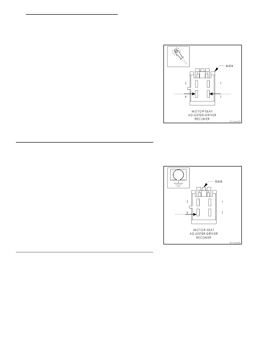
CHECK THE (G403) DRIVER SEAT RECLINER POSITION
SENSE VOLTAGE
Disconnect the Driver Recliner Seat Adjuster Motor.
Note: Check connectors – Clean and repair as necessary.
Move the seat switch in the recliner position during the next step.
Using a 12-volt test light connect one lead to the (G403) Driver Seat
Recliner Position Sense circuit and the other lead to Driver Seat
Recliner Position Sensor Ground at the Driver Recliner Seat Adjuster
Motor connector.
Does the test light illuminate for approximately 2 seconds then
turn off with the seat switch engaged?
Yes
>> Replace the Driver Recliner Seat Adjuster Motor assem-
bly.
Perform POWER SEAT SYSTEM VERIFICATION TEST –
VER 1
No
>> Go To 3
3.
CHECK THE (G403) DRIVER SEAT RECLINER POSITION
SENSE WIRE FOR A SHORT TO GROUND
Disconnect the Seat Memory Module C2 connector.
Note: Check connectors – Clean and repair as necessary.
Measure the resistance of the (G403) Driver Seat Recliner Position
Sense wire at the Driver Recliner Seat Adjuster Motor connector to
ground.
Is the resistance below 1000.0 ohm?
Yes
>> Repair the (G403) Driver Seat Recliner Position Sense cir-
cuit for a short to ground.
Perform POWER SEAT SYSTEM VERIFICATION TEST –
VER 1
No
>> Replace the Seat Memory Module.
Perform POWER SEAT SYSTEM VERIFICATION TEST –
VER 1
HB
POWER SEATS - ELECTRICAL DIAGNOSTICS
8N - 173
B1D79–SEAT BACKREST POSITION SENSOR CIRCUIT LOW —
(CONTINUED)