Dodge Durango (HB). Manual - part 398
HB
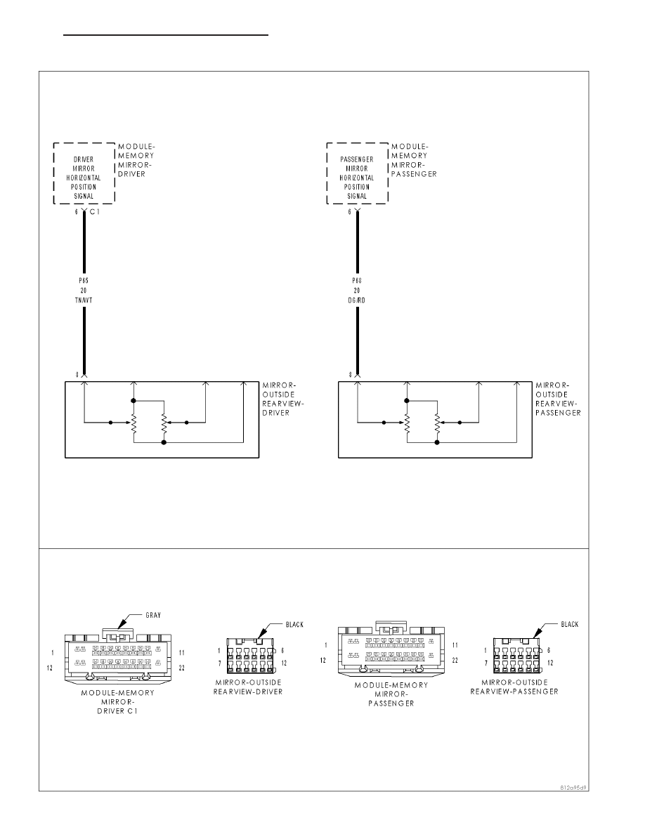
POWER MIRRORS - ELECTRICAL DIAGNOSTICS
8N - 105
B1D10,B1D19–MIRROR HORIZONTAL POSITION SENSOR INPUT CIRCUIT HIGH – MEMORY MIRROR MODULE
|
|
|
HB POWER MIRRORS - ELECTRICAL DIAGNOSTICS 8N - 105 B1D10,B1D19–MIRROR HORIZONTAL POSITION SENSOR INPUT CIRCUIT HIGH – MEMORY MIRROR MODULE |