Dodge Durango (HB). Manual - part 383


  Index      Dodge     Dodge Durango (HB) - service repair manual 2005 year


Search            


Content   ..  381  382  383  384   ..


Dodge Durango (HB). Manual - part 383


2.

DRIVER MODULE OR PASSENGER MODULE

Is this DTC in the Driver or Passenger module?

Passenger

Go to 3

Driver

Go to 5

3.

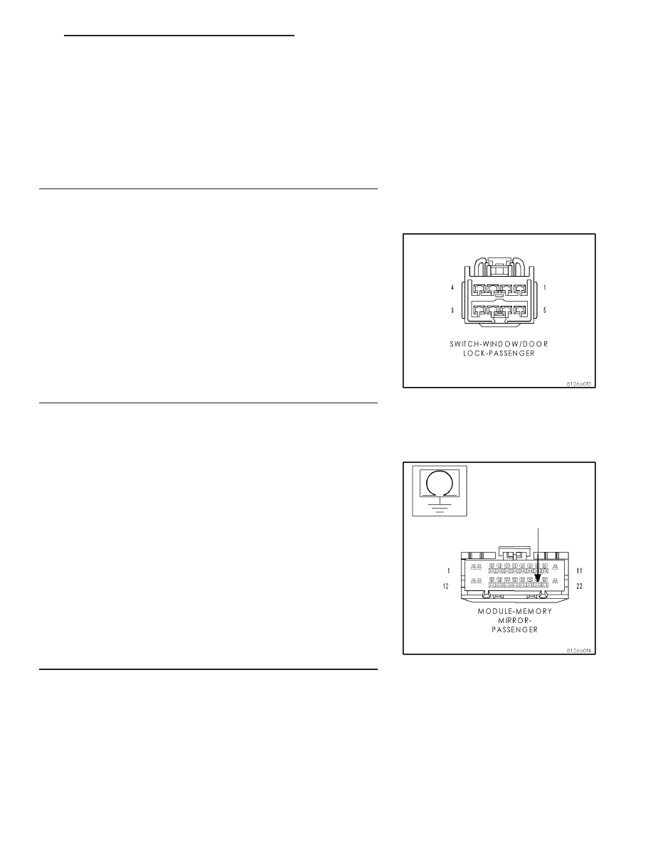
PASSENGER DOOR LOCK SWITCH SHORTED TO GROUND

With the scan tool, erase DTC’s.

Disconnect the Passenger Window/Door Lock Switch connector.

Turn the ignition on.

With the scan tool, read DTC’s.

Does the scan tool display DOOR LOCK/UNLOCK SWITCH CIR-
CUIT STUCK UNLOCK?

No

>> Replace the Passenger Window/Door Lock Switch.

Perform BODY VERIFICATION TEST - VER 1.

Yes

>> Go to 4

4.

(G160) PASSENGER DOOR LOCK SWITCH MUX CIRCUIT
SHORT TO GROUND

Disconnect the Passenger Memory Mirror Module connector.

Measure the resistance between ground and the (G160) Passenger
Door Lock Switch Mux circuit in the Passenger Memory Mirror Module
connector.

Is the resistance below 10000.0 ohms?

Yes

>> Repair the (G160) Passenger Door Lock Switch Mux cir-

cuit for a short to ground.

Perform BODY VERIFICATION TEST - VER 1.

No

>> Replace the Passenger Memory Mirror Module.

Perform BODY VERIFICATION TEST - VER 1.

HB

POWER LOCKS - ELECTRICAL DIAGNOSTICS

8N - 45

B1804, B1809 DOOR LOCK/UNLOCK SWITCH CIRCUIT STUCK UNLOCK – MEMORY MIRROR MODULE — (CONTINUED)

5.

DRIVER DOOR LOCK SWITCH SHORTED TO GROUND

With the scan tool, erase DTC’s.

Disconnect the Driver Window/Door Lock Switch connector.

Turn the ignition on.

With the scan tool, read DTC’s.

Does the scan tool display DOOR LOCK/UNLOCK SWITCH CIR-
CUIT STUCK UNLOCK?

No

>> Replace the Driver Window/Door Lock Switch.

Perform BODY VERIFICATION TEST - VER 1.

Yes

>> Go to 6

6.

(G161) DRIVER DOOR LOCK SWITCH MUX WIRE SHORT TO
GROUND

Disconnect the Driver Memory Mirror Module C1 connector.

Measure the resistance between ground and the (G161) Driver Door
Lock Switch Mux circuit in the Memory Mirror Module connector.

Is the resistance below 10000.0 ohms?

Yes

>> Repair the (G161) Driver Door Lock Switch Mux circuit for

a short to ground.

Perform BODY VERIFICATION TEST - VER 1.

No

>> Go to 7

7.

MEMORY SELECT MUX WIRE SHORT TO GROUND

Disconnect the Driver Memory Mirror Module C2 connector.

Measure the resistance between ground and the Memory Select
Switch Mux circuit.

Is the resistance below 10000.0 ohms?

Yes

>> Repair the Memory Select Switch Mux wire for a short to

ground.

Perform the BODY VERIFICATION TEST - VER 1.

No

>> Go to 8

8N - 46

POWER LOCKS - ELECTRICAL DIAGNOSTICS

HB

B1804, B1809 DOOR LOCK/UNLOCK SWITCH CIRCUIT STUCK UNLOCK – MEMORY MIRROR MODULE — (CONTINUED)

8.

MEMORY SELECT SWITCH MUX CIRCUIT SHORTED

Measure the resistance between the Memory Select Switch Mux cir-
cuit and the Memory Select Switch Return circuit in the Driver Memory
Mirror Module C2 connector.

Is the resistance below 10000.0 ohms?

Yes

>> Go to 9

No

>> Replace the Driver Memory Mirror Module.

Perform BODY VERIFICATION TEST - VER 1.

9.

MEMORY SELECTOR SWITCH SHORTED

Disconnect the Memory Selector Switch connector.

Measure the resistance between the (P339) Memory Select Switch
Mux circuit and the (G920) Memory Select Switch Return circuit in the
Driver Memory Mirror Module C2 connector.

Is the resistance below 10000.0 ohms?

Yes

>> Repair the (P339) Memory Select Switch Mux circuit for a

short to the (G920) Memory Select Switch Return circuit.

Perform the BODY VERIFICATION TEST - VER 1.

No

>> Replace the Memory Selector Switch.

Perform BODY VERIFICATION TEST - VER 1.

HB

POWER LOCKS - ELECTRICAL DIAGNOSTICS

8N - 47

B1804, B1809 DOOR LOCK/UNLOCK SWITCH CIRCUIT STUCK UNLOCK – MEMORY MIRROR MODULE — (CONTINUED)

Diagnostic Test

1.

Perform Body Verification Test

Disconnect all jumper wires and reconnect all previously disconnected
components and connectors.

Ensure that all accessories are turned off.

Ensure that the battery is fully charged.

Turn the ignition on.

With the scan tool, record and erase DTCs from all modules.

If repairs were made to any of the HVAC door actuator circuits, with
the scan tool in HVAC, select System Tests and then select Actuator
DTC Detection. The test must pass before proceeding to the next
step.

If repairs were made to any of the HVAC doors, linkage, door actua-
tors, or door actuator circuits, with the scan tool in HVAC, select Sys-
tem Tests and then select Actuator Calibration Test. The test must
pass before proceeding to the next step.

Turn the ignition off, wait 10 seconds, and then turn the ignition on.

Operate all functions of the system that caused the original concern.

With the scan tool, select ECU View.

Check for DTCs in the modules.

Are DTCs present in any of the modules or is the original con-
dition still present?

Yes

>> The repair is not complete. Refer to the related category

for the DTC or symptom that is still present.

No

>> The repair is complete.

8N - 48

POWER LOCKS - ELECTRICAL DIAGNOSTICS

HB

BODY VERIFICATION TEST – VER 1


Content   ..  381  382  383  384   ..