Dodge Durango (HB). Manual - part 380


  Index      Dodge     Dodge Durango (HB) - service repair manual 2005 year


Search            


Content   ..  378  379  380  381   ..


Dodge Durango (HB). Manual - part 380


2.

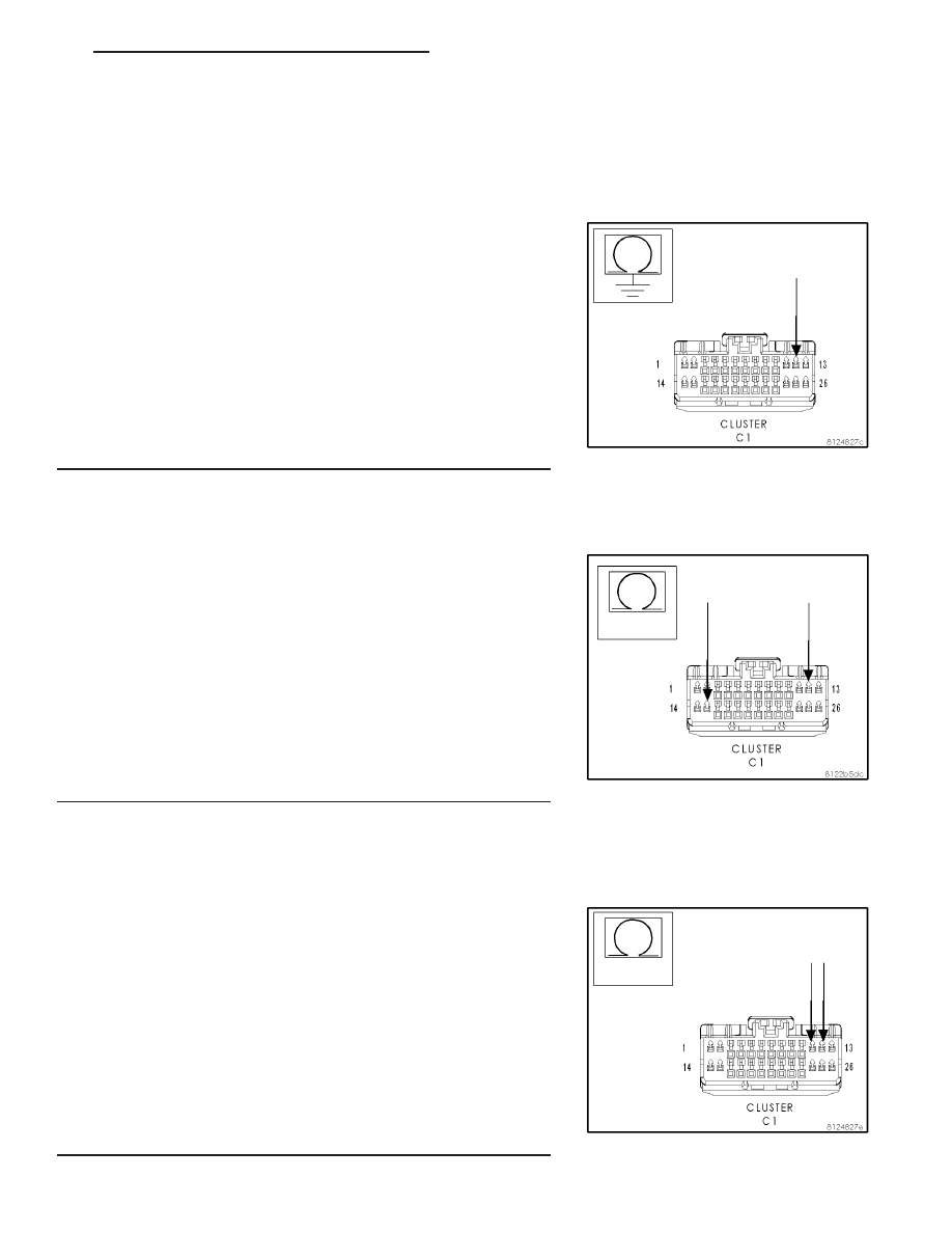
CHECK (P1) DOOR UNLOCK DRIVER LEFT FRONT FOR
SHORT TO GROUND

Note: If only one motor is inoperative when the door locks are
actuated, disconnect that motor and retest to see if the DTC is
still present. If it is not, replace the defective motor.

Turn the ignition off.

Disconnect the Cluster C1 connector.

Measure the resistance between ground and the (P1) Door Unlock
Driver Left Front circuit.

Is the resistance below 1000.0 ohms?

No

>> Go To 3

Yes

>> Repair the (P1) Door Unlock Driver Left Front circuit for a

short to ground.

Perform BODY VERIFICATION TEST - VER 1.

3.

CHECK THE (P1) DOOR UNLOCK DRIVER LEFT FRONT FOR
A SHORT TO THE (P393) DOOR LOCK DRIVER LEFT DOORS

Measure the resistance between the (P1) Door Unlock Driver Left
Front and the (P393) Door Lock Driver Left Doors circuits.

Is the resistance below 2.0 ohms?

No

>> Go To 4

Yes

>> Repair the (P1) Door Unlock Driver Left Front circuit for a

short to the (P393) Door Lock Driver Left Doors circuit.

Perform BODY VERIFICATION TEST - VER 1.

4.

CHECK THE (P1) DOOR UNLOCK DRIVER LEFT FRONT
CIRCUIT FOR A SHORT TO THE (P5) DOOR UNLOCK DRIVER
LEFT REAR/LIFTGATE CIRCUIT

Measure the resistance between the (P1) Door Unlock Driver Left
Front circuit and the (P5) Door Unlock Driver Left Rear/Liftgate circuit.

Is the resistance below 3.0 ohms?

No

>> Replace the Instrument Cluster in accordance with service

information.Perform BODY VERIFICATION TEST - VER 1.

Yes

>> Repair the (P1) Door Unlock Driver Left Front circuit for a

short to the (P5) Door Unlock Driver Left Rear/Liftgate cir-
cuit.

Perform BODY VERIFICATION TEST - VER 1.

HB

POWER LOCKS - ELECTRICAL DIAGNOSTICS

8N - 33

B1835-DRIVER DOOR UNLOCK OUTPUT CIRCUIT SHORTED TO GROUND — CLUSTER — (CONTINUED)

8N - 34

POWER LOCKS - ELECTRICAL DIAGNOSTICS

HB

B1802, B1807 DOOR LOCK/UNLOCK SWITCH CIRCUIT HIGH – MEMORY MIRROR MODULE

For the Power Door Lock circuit diagram (Refer to 8 - ELECTRICAL/POWER LOCKS - SCHEMATICS AND DIA-
GRAMS)

For a complete wiring diagram Refer to Section 8W.

When Monitored:
Continuously

Set Condition:
When the Door Lock Switch Mux circuit is above 5.25 volts for over 30 msec.

Possible Causes

(G160, G161) DOOR LOCK SWITCH MUX WIRE SHORT TO VOLTAGE

(P339) MEMORY SELECT SWITCH MUX WIRE SHORT TO VOLTAGE

WINDOW/DOOR LOCK SWITCH

MEMORY MIRROR MODULE

Theory of Operation

This code will only set in vehicles that have the Memory System. The supply circuit for the Memory Mirrors are
supplied by the Memory Mirror Module, therefore both the Memory Select Switch Mux or the Door Lock Switch Mux
circuits can cause this DTC.

Diagnostic Test

1.

TEST FOR INTERMITTENT CONDITION

With the scan tool, record and erase DTC’s

Operate the Door Lock Switch from the side this DTC was set in. Put
the switch in both positions several times.

Cycle the ignition from on to off 3 times.

Turn the ignition on.

With the scan tool, read DTC’s.

Does the scan tool display DOOR LOCK/UNLOCK SWITCH CIR-
CUIT HIGH?

Yes

>> Go To 2

No

>> The conditions that caused this code to set are not

present at this time. Using the wiring diagram/schematic
as a guide, inspect the wiring and connectors.

Perform BODY VERIFICATION TEST - VER 1.

HB

POWER LOCKS - ELECTRICAL DIAGNOSTICS

8N - 35

B1802, B1807 DOOR LOCK/UNLOCK SWITCH CIRCUIT HIGH – MEMORY MIRROR MODULE — (CONTINUED)

2.

DOOR LOCK SWITCH SHORTED TO VOLTAGE

With the scan tool, erase DTC’s.

Disconnect the appropriate Window/Door Lock Switch connector.

Turn the ignition on.

With the scan tool, read DTC’s.

Does the scan tool display DOOR LOCK/UNLOCK SWITCH CIR-
CUIT HIGH?

No

>> Replace the Window/Door Lock Switch.

Perform BODY VERIFICATION TEST - VER 1.

Yes

>> Go to 3

3.

DRIVER MODULE OR PASSENGER MODULE

Is this DTC in the Driver or Passenger module?

Passenger

Go to 4

Driver

Go to 5

4.

(G160) PASSENGER DOOR LOCK SWITCH MUX CIRCUIT
SHORT TO VOLTAGE

Disconnect the Passenger Memory Mirror Module connector.

Measure the voltage of the (G160) Passenger Door Lock Switch Mux
circuit in the Passenger Memory Mirror Module connector.

Is there any voltage present?

Yes

>> Repair the (G160) Passenger Door Lock Switch Mux cir-

cuit for a short to voltage.

Perform BODY VERIFICATION TEST - VER 1.

No

>> Replace the Passenger Memory Mirror Module.

Perform BODY VERIFICATION TEST - VER 1.

8N - 36

POWER LOCKS - ELECTRICAL DIAGNOSTICS

HB

B1802, B1807 DOOR LOCK/UNLOCK SWITCH CIRCUIT HIGH – MEMORY MIRROR MODULE — (CONTINUED)


Content   ..  378  379  380  381   ..