Dodge Durango (HB). Manual - part 285


  Index      Dodge     Dodge Durango (HB) - service repair manual 2005 year


Search            


Content   ..  283  284  285  286   ..


Dodge Durango (HB). Manual - part 285


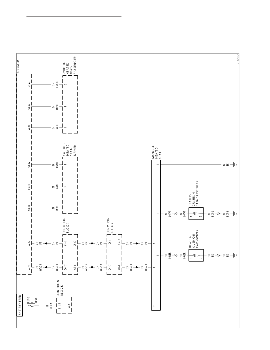
SCHEMATICS AND DIAGRAMS

HEA

TED

SEA

T

SYSTEM

SCHEMA

TIC

HB

HEATED SEATS - ELECTRICAL DIAGNOSTICS

8G - 87

HEATED SEATS - SERVICE INFORMATION

TABLE OF CONTENTS

page

page

HEATED SEATS - SERVICE INFORMATION

DESCRIPTION

HEATED SEAT SYSTEM

. . . . . . . . . . . . . . . . 88

OPERATION

HEATED SEAT SYSTEM

. . . . . . . . . . . . . . . . 89

DIAGNOSIS AND TESTING

HEATED SEAT SYSTEM

. . . . . . . . . . . . . . . . 89

HEATER-CUSHION PAD

DESCRIPTION

. . . . . . . . . . . . . . . . . . . . . . . . . 90

OPERATION

. . . . . . . . . . . . . . . . . . . . . . . . . . . 90

DIAGNOSIS AND TESTING

HEATED SEAT ELEMENT

. . . . . . . . . . . . . . . 91

REMOVAL

. . . . . . . . . . . . . . . . . . . . . . . . . . . . . 91

INSTALLATION

. . . . . . . . . . . . . . . . . . . . . . . . . 92

MODULE-HEATED SEAT

DESCRIPTION

. . . . . . . . . . . . . . . . . . . . . . . . . 92

OPERATION

. . . . . . . . . . . . . . . . . . . . . . . . . . . 93

DIAGNOSIS AND TESTING

HEATED SEAT MODULE

. . . . . . . . . . . . . . . . 93

REMOVAL

. . . . . . . . . . . . . . . . . . . . . . . . . . . . . 93

INSTALLATION

. . . . . . . . . . . . . . . . . . . . . . . . . 94

SWITCH-HEATED SEAT

DESCRIPTION

HEATED SEAT SWITCH

. . . . . . . . . . . . . . . . 94

OPERATION

HEATED SEAT SWITCH

. . . . . . . . . . . . . . . . 95

DIAGNOSIS AND TESTING

HEATED SEAT SWITCH

. . . . . . . . . . . . . . . . 95

REMOVAL

. . . . . . . . . . . . . . . . . . . . . . . . . . . . . 97

INSTALLATION

. . . . . . . . . . . . . . . . . . . . . . . . . 98

HEATED SEATS - SERVICE INFORMATION

DESCRIPTION

HEATED SEAT SYSTEM

Vehicles with the heated seat option can be visually identified by the two heated seat switches located in the center
stack of the instrument panel. The heated seat system allows the driver and front seat passenger to select from two
different levels of electrical seat heating (HI/LO). The heated seat system for this vehicle includes the following
major components, which are described in further detail later in this section:

Heated Seat Elements - Four heated seat elements are used per vehicle. Two heated seat elements are
integral to each seat, one in the seat back and the other in the seat cushion.

Heated Seat Module - One heated seat module is used per vehicle. The Heated Seat Module is mounted
behind the right rear D-pillar trim panel. This module contains the control logic and software for the front
heated seat system. The module also communicates on the CAN data bus network.

Heated Seat Switches - Two heated seat switches are used per vehicle, one for each heated seat. Both
switches are mounted in the instrument panel center stack.

Instrument Cluster (CCN) - A Cab Compartment Node (CCN) is part of the instrument cluster on this vehi-
cle. The CCN utilizes integrated software and information carried on the CAN data bus network. The Cab
Compartment Node (CCN) serves as the link between the heated seat switches and the heated seat
module.

8G - 88

HEATED SEATS - SERVICE INFORMATION

HB

OPERATION

HEATED SEAT SYSTEM

The heated seat system operates on battery current received through a fuse in the Integrated Power Module (IPM).
Fused ignition switch output (run-acc) circuits are used, so that the heated seat system will only operate when the
ignition switch is in the On or Accessory positions. The heated seat system will turn Off automatically whenever the
ignition switch is turned to any position except On or Accessory.

A Heated Seat Module is used to control the heated seat system. The module responds to heated seat switch
messages and ignition switch status inputs by controlling the 12v output to the front seat heating elements through
integral solid-state relays.

When either of the heated seat switches are depressed a resistance signal is sent to the Cab Compartment Node
(CCN) or instrument cluster. The Cab Compartment Node (CCN) then sends a CAN bus message to the heated
seat module, signaling the module to energize the heating element for the selected seat. The Cab Compartment
Node (CCN) also turns on the HI and LO LED indicators on each of the heated seat switches.

The heated seat module energizes an integral solid-state relay, which supplies battery current to the heating ele-
ments. When the pre-programmed duty-cycle has been achieved (approx. 2 hours), the module de-energizes the
solid-state relay. The module will continue to cycle the solid-state relay as needed to maintain the temperature set
point. No heated seat sensors are used with the heated seat system option.

The module will automatically turn off the heating elements if it detects an OPEN or LOW short in the heating
element circuit. See the owner’s manual in the vehicle glove box for more information on the features, use and
operation of the heated seat system.

DIAGNOSIS AND TESTING

HEATED SEAT SYSTEM

In order to obtain conclusive testing of the heated seat system, the Controller Area Network (CAN) data bus system
must be checked.

The most reliable, efficient, and accurate means to diagnose the heated seat system requires the use of a Scan
Tool and the Service and Body Diagnostic Information. The Scan Tool can provide vital information to the technician
trying to find a problem with the heated seat system. Diagnostic logic is built into the heated seat module and the
instrument cluster (CCN) to help the person trying to locate the problem by the most efficient means possible. Any-
time a problem is suspected, a Scan Tool should be obtained and used to retrieve any stored fault codes in the
heated seat module and/or instrument cluster.

If diagnostic fault codes are present in the module, record them on a piece of paper immediately before proceeding
any further. Then, use these fault codes to identify the problem by verifying the fault code. Example, If the module
records “DRIVER SEAT HEAT OUTPUT OPEN” fault code, locate the diagnostic procedure for this code in the
appropriate Body Diagnostic information and follow the steps until the specific problem is located and resolved.
Once the problem is thought to be corrected, erase the stored fault code using the Scan Tool and verify correct
system operation. If the heated seat system is functioning correctly, verify that there are no other stored codes in
the module and return the vehicle to service.

If the fault code could not be verified, such as not finding anything wrong when following the diagnostic steps in the
Body Diagnostic information. This is a good indication that a INTERMITTENT problem may be present. You must
than attempt to find the intermittent problem, such as moving the heating element within the seat while testing con-
tinuity or wiggling the wire harness/electrical connectors under the seat while testing continuity. Always, eliminate all
other potential problems before attempting to replace module.

HB

HEATED SEATS - SERVICE INFORMATION

8G - 89

PRELIMINARY TEST

Before testing the individual components in the heated seat system, check the following:

Using Scan Tool, check the heated seat module for any stored fault codes. Record these codes on paper
for reference and resolve using the appropriate Body Diagnostic information.

Check the vehicles battery open-circuit voltage and charging system performance. If the vehicles electrical
system is defective or weak it may not be suppling sufficient energy to operate the heated seat system.

If the heated seat switch backlighting does not light with the ignition switch in the On position, check the
fused ignition switch fuse in the integrated power module. If OK, (Refer to 8 - ELECTRICAL/HEATED
SEATS/SEAT SWITCH - DIAGNOSIS AND TESTING). If not OK, repair the shorted circuit or component as
required and replace the faulty fuse or repair the open ground circuit as required.

If the heated seat switch HI/LO LED indicators do not light with the ignition switch in the On position and the
heated seat switch in the Low or High position, check the fused ignition switch fuse in the integrated power
module. If OK, (Refer to 8 - ELECTRICAL/HEATED SEATS/SEAT SWITCH - DIAGNOSIS AND TESTING).
If not OK, repair the shorted circuit or component as required and replace the faulty fuse.

HEATER-CUSHION PAD

DESCRIPTION

Vehicles equipped with the optional heated seat system have two heated seat element located in each front seat.
One heating element is used for each seat cushion and another for each seat back.

Each of the heated seat element consists of a single length of resistor wire that is routed in a zigzag pattern and
captured between the leather trim cover and the seat cushion assembly. Short pigtail wires with connectors are
soldered to each end of each resistor wire element grid, which connect all of the element grids to each other in
series with the heated seat module through the wire harness.

The heated seat elements cannot be repaired. If found to be damaged or faulty, a new heating element assembly
must be installed.

OPERATION

One end of the heated seat element resistor wire is connected to ground at all times through a splice under the
seat. Battery current is directed to the other end of the heated seat element resistor wire by the energized N-chan-
nel Field Effect Transistor located within the heated seat module. The heated seat module will energize the N-FET
when the heated seat switch is depressed in the Low or High position.

As electrical current passes through the heating element grid, the resistance of the wire used in the element dis-
perses some of that electrical current in the form of heat. The heat produced by the heated seat element grid then
radiates through the underside of the seat cushion and seat back trim covers, warming the seat cover and its
occupant.

8G - 90

HEATED SEATS - SERVICE INFORMATION

HB


Content   ..  283  284  285  286   ..