Dodge Durango (HB). Manual - part 187


  Index      Dodge     Dodge Durango (HB) - service repair manual 2005 year


Search            


Content   ..  185  186  187  188   ..


Dodge Durango (HB). Manual - part 187


TEST 2

Test 2 checks the antenna for an open circuit as follows:

1. Disconnect the antenna coaxial cable connector from the radio receiver chassis.

2. Connect one ohmmeter test lead to the antenna mast in the center of the antenna base. Connect the other test

lead to the center pin of the antenna coaxial cable connector.

3. Continuity should exist (the ohmmeter should only register a fraction of an ohm). High or infinite resistance indi-

cates damage to the base and cable assembly. Replace the faulty base and cable, if required.

TEST 3

Test 3 checks the condition of the vehicle body ground connection. This test should be performed with the battery
positive cable removed from the battery. Disconnect both battery cables, the negative cable first. Reconnect the
battery negative cable and perform the test as follows:

1. Connect one ohmmeter test lead to the vehicle fender. Connect the other test lead to the battery negative ter-

minal post.

2. The resistance should be less than one ohm.

3. If the resistance is more than one ohm, check the braided ground strap(s) connected to the engine and the

vehicle body for being loose, corroded, or damaged. Repair the ground strap connections, if required.

TEST 4

Test 4 checks the condition of the ground between the antenna base and the vehicle body as follows:

1. Connect one ohmmeter test lead to the vehicle fender. Connect the other test lead to the outer crimp on the

antenna coaxial cable connector.

2. The resistance should be less then one ohm.

3. If the resistance is more then one ohm, clean and/or tighten the antenna base to fender mounting hardware.

REMOVAL

1. Disconnect and isolate the battery negative cable.

2. Remove the right side cowl trim cover.

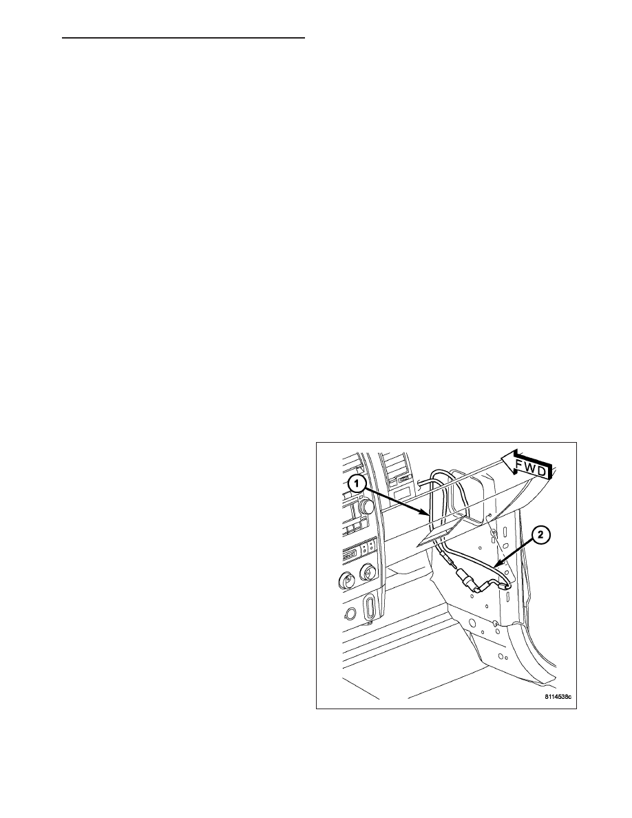
3. Reach under the instrument panel outboard of the

glove box to access and disconnect the antenna
coaxial cable connector (2). Disconnect the con-
nector by pulling it apart while twisting the metal
connector halves. Do not pull on the cable.

4. Disengage the antenna coaxial cable retainer at

the right cowl side inner panel.

HB

AUDIO/VIDEO - SERVICE INFORMATION

8A - 189

5. Remove the right side wheelhouse splash shield.

6. Unscrew the antenna mast (2) from the antenna

body.

7. Remove the antenna cap nut (3) using an antenna

nut wrench (Special Tool C-4816)

8. Remove the antenna adapter (4) from the top of

the fender.

9. Lower the antenna body (5) through the mounting

hole in the top of the fender.

10. Disengage the antenna coaxial cable grommet

from the hole in the right cowl side outer panel.

11. Pull the antenna body and cable out through the

opening between the right cowl side outer panel
and the fender.

INSTALLATION

1. Position the antenna body and cable (5) in the

opening between the right cowl side outer panel
and the fender.

2. Push the antenna coaxial cable into the passenger

compartment through the hole in the right cowl side
outer panel.

3. Engage the antenna coaxial cable grommet in the

hole in the right cowl side outer panel.

4. Position the antenna body through the mounting

hole in the top of the fender.

5. Install the adapter (4) over the antenna body from

the top of the fender.

6. Install and tighten the antenna cap nut (3) using an

antenna nut wrench (Special Tool C-4816).

7. Install and tighten the antenna mast (2) onto the

antenna body.

8. Engage the antenna coaxial cable retainers at the

right cowl side inner panel and inside the right front
fender.

8A - 190

AUDIO/VIDEO - SERVICE INFORMATION

HB

9. Engage the antenna coaxial cable in the retainer

clips on the lower instrument panel support and the
glovebox.

10. Reach under the instrument panel outboard of the

glove box to reconnect the antenna coaxial cable
connector (2).

11. Install the cowl trim cover.

12. Install the wheelhouse splash shield.

13. Connect the battery negative cable.

ANTENNA - NAVIGATION RADIO

REMOVAL

WARNING: To avoid personal injury or death, on vehicles equipped with airbags, disable the supplemental
restraint system before attempting any steering wheel, steering column, airbag, occupant classification sys-
tem, seat belt tensioner, impact sensor, or instrument panel component diagnosis or service. Disconnect
and isolate the battery negative (ground) cable, then wait two minutes for the system capacitor to discharge
before performing further diagnosis or service. This is the only sure way to disable the supplemental
restraint system. Failure to take the proper precautions could result in accidental airbag deployment.

1. Disconnect and isolate the battery negative cable.

2. Remove the radio (Refer to 8 - ELECTRICAL/AU-

DIO/RADIO - REMOVAL).

3. Remove the instrument panel defroster grille (Refer

to 23 - BODY/INSTRUMENT PANEL/DEFROSTER
GRILLE - REMOVAL).

4. Remove the passenger airbag (Refer to 8 - ELEC-

TRICAL/RESTRAINTS/PASSENGER

AIRBAG

-

REMOVAL).

5. Remove the antenna mounting fasteners

.

HB

AUDIO/VIDEO - SERVICE INFORMATION

8A - 191

6. Remove the navigation radio antenna .

INSTALLATION

WARNING: To avoid personal injury or death, on vehicles equipped with airbags, disable the supplemental
restraint system before attempting any steering wheel, steering column, airbag, occupant classification sys-
tem, seat belt tensioner, impact sensor, or instrument panel component diagnosis or service. Disconnect
and isolate the battery negative (ground) cable, then wait two minutes for the system capacitor to discharge
before performing further diagnosis or service. This is the only sure way to disable the supplemental
restraint system. Failure to take the proper precautions could result in accidental airbag deployment.

1. Position antenna to instrument panel.

2. Connect antenna to radio.

3. Install radio (Refer to 8 - ELECTRICAL/AUDIO/RA-

DIO - INSTALLATION).

8A - 192

AUDIO/VIDEO - SERVICE INFORMATION

HB


Content   ..  185  186  187  188   ..