Index Dodge Dodge Durango (HB) - service repair manual 2005 year
Search
Content .. 184 185 186 187 ..
Dodge Durango (HB). Manual - part 186
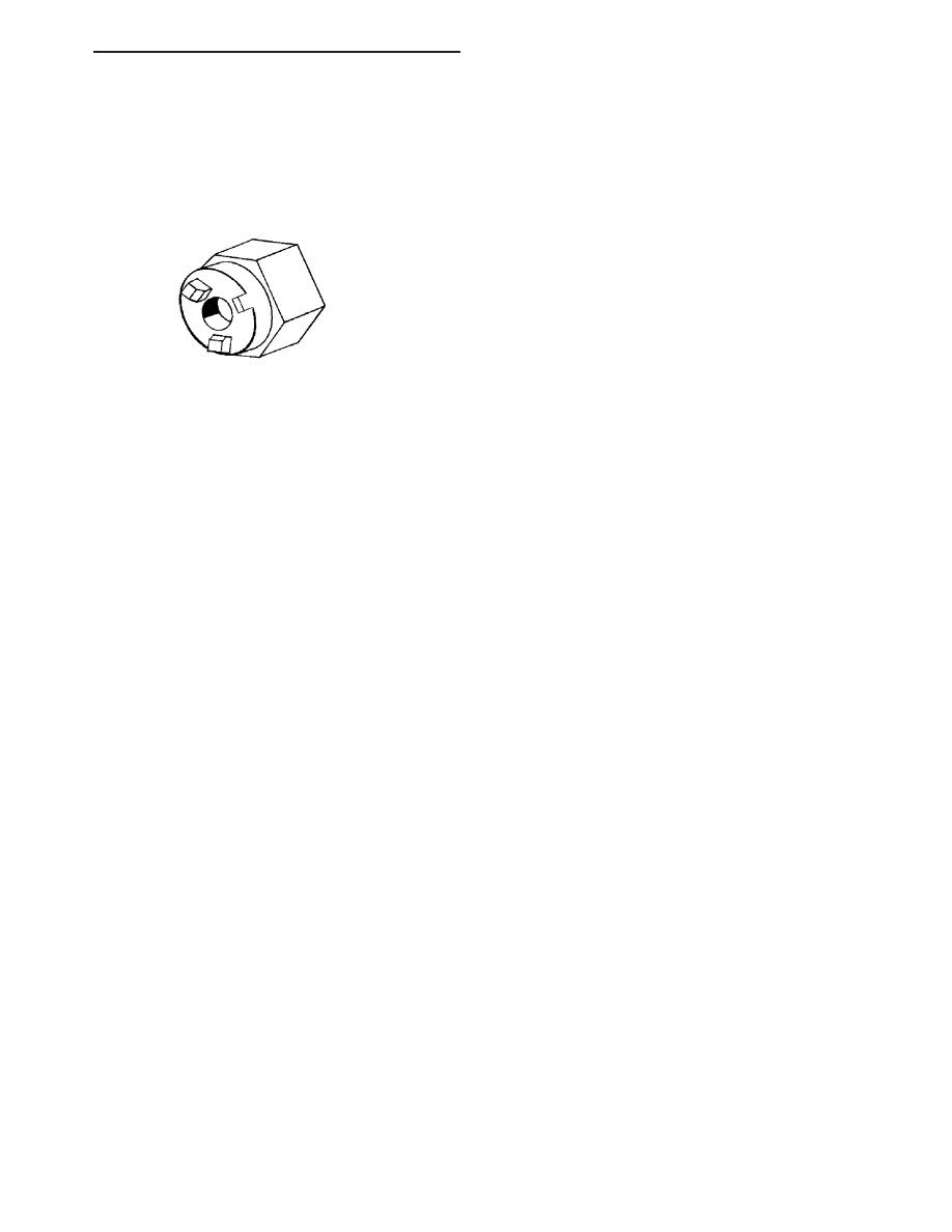
SPECIAL TOOLS
AUDIO SYSTEMS
HB
AUDIO/VIDEO - SERVICE INFORMATION
8A - 185