Index Dodge Dodge Durango (HB) - service repair manual 2005 year
Search
Content .. 182 183 184 185 ..
Dodge Durango (HB). Manual - part 184
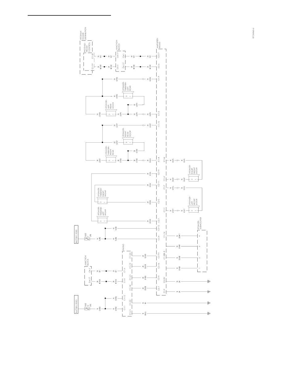
PREMIUM
RADIO
SYSTEM
HB
AUDIO/VIDEO SYSTEMS - ELECTRICAL DIAGNOSIS
8A - 177