Dodge Durango (HB). Manual - part 1568


  Index      Dodge     Dodge Durango (HB) - service repair manual 2005 year


Search            


Content   ..  1566  1567  1568  1569   ..


Dodge Durango (HB). Manual - part 1568


NOTE: Liquid CO

2

is required to test the A/C expansion valve. This material is available from most welding

supply facilities. Liquid CO

2

is also available from companies which service and sell fire extinguishers.

When testing the A/C expansion valve, the work area and the vehicle temperature must be 21° to 27° C (70° to 85°
F). To test the expansion valve:

1. Connect a charging station or manifold gauge set to the refrigerant system service ports. Verify the refrigerant

charge level.

2. Close all doors, windows and vents to the passenger compartment.

3. Set the A/C-heater controls so that the A/C compressor is operating, the temperature control is in the highest

temperature position, the mode-air doors is directing air output to the floor and the blower motor operating is
operating at the highest speed.

4. Start the engine and allow it to idle. After the engine has reached normal operating temperature, allow the pas-

senger compartment to heat up. This will create the need for maximum refrigerant flow into the A/C evaporator.

5. If the refrigerant charge is sufficient, the discharge (high pressure) gauge should read 827 kPa to 1655 kPa (120

psi to 240 psi). The suction (low pressure) gauge should read 207 kPa to 345 kPa (30 psi to 50 psi). If OK, go
to Step 6. If not OK, replace the faulty A/C expansion valve.

WARNING:
Protect the skin and eyes from exposure to liquid CO

2

or personal injury can result.

6. If the suction (low pressure) gauge reads within the specified range, freeze the A/C expansion valve for 30 sec-

onds using liquid CO

2

or another suitable super-cold material.Do not spray R-134a or R-12 refrigerant on the

A/C expansion valve for this test. The suction (low pressure) gauge reading should drop by 69 kPa (10 psi).
If OK, go to Step 7 If not OK, replace the faulty A/C expansion valve.

7. Allow the expansion valve control head to thaw. The suction (low pressure) gauge reading should stabilize at 207

kPa to 345 kPa (30 psi to 50 psi). If not OK, replace the faulty A/C expansion valve.

8. When expansion valve testing is complete, test the overall A/C system performance (Refer to 24 - HEATING &

AIR CONDITIONING - DIAGNOSIS AND TESTING - A/C PERFORMANCE TEST).

REMOVAL

WARNING: Refer to the applicable warnings and cautions for this system before performing the following
operation (Refer to 24 - HEATING & AIR CONDITIONING/PLUMBING - FRONT - WARNINGS) and (Refer to 24
- HEATING & AIR CONDITIONING/PLUMBING - FRONT - CAUTIONS). Failure to follow the warnings and cau-
tions could result in possible personal injury or death.

1. Recover the refrigerant from the refrigerant system

(Refer to 24 - HEATING & AIR CONDITIONING/
PLUMBING - FRONT - STANDARD PROCEDURE
- REFRIGERANT SYSTEM RECOVERY).

2. Disconnect and isolate the negative battery cable.

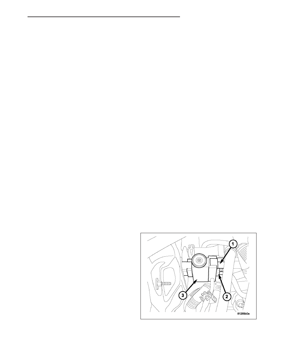
3. Remove the A/C suction line (1) and the A/C liquid

line (2) from the A/C expansion valve (3) (Refer to
24 - HEATING & AIR CONDITIONING/PLUMBING
- FRONT/LINE-A/C SUCTION - REMOVAL) or
(Refer to 24 - HEATING & AIR CONDITIONING/
PLUMBING

-

FRONT/LINE-A/C

LIQUID

-

REMOVAL).

HB

PLUMBING - FRONT

24 - 465

4. Remove the two bolts (1) that secure the A/C

expansion valve (2) to the evaporator tube tapping
block (3).

5. Remove the A/C expansion valve from the evapo-

rator tube tapping block and remove and discard
the O-ring seals.

6. Install plugs in, or tape over the opened evaporator

tube fittings and all expansion valve ports.

INSTALLATION

1. Remove the tape or plugs from the evaporator tube

fittings and all of the expansion valve ports.

2. Lubricate new rubber O-ring seals with clean refrig-

erant oil and install them on the evaporator tube fit-
tings. Use only the specified O-rings as they are
made of a special material for the R-134a system.
Use only refrigerant oil of the type recommended
for the A/C compressor in the vehicle.

3. Install the A/C expansion valve (2) onto the evapo-

rator tube tapping block (3).

4. Install the two bolts (1) that secure the A/C expan-

sion valve to the evaporator tube tapping block.
Tighten the bolts to 11 N·m (97 in. lbs.).

5. Install the A/C suction line (1) and the A/C liquid

line (2) to the A/C expansion valve (3) (Refer to 24
- HEATING & AIR CONDITIONING/PLUMBING -
FRONT/LINE-A/C SUCTION - INSTALLATION) or
(Refer to 24 - HEATING & AIR CONDITIONING/
PLUMBING - FRONT/LINE-A/C LIQUID - INSTAL-
LATION).

6. Reconnect the negative battery cable.

7. Evacuate the refrigerant system (Refer to 24 -

HEATING & AIR CONDITIONING/PLUMBING -
FRONT - STANDARD PROCEDURE - REFRIGER-
ANT SYSTEM EVACUATE).

8. Recharge the refrigerant system (Refer to 24 -

HEATING & AIR CONDITIONING/PLUMBING -
FRONT - STANDARD PROCEDURE - REFRIGER-
ANT SYSTEM CHARGE).

24 - 466

PLUMBING - FRONT

HB

PLUMBING - REAR

TABLE OF CONTENTS

page

page

CORE-HEATER

DESCRIPTION

. . . . . . . . . . . . . . . . . . . . . . . . 467

OPERATION

. . . . . . . . . . . . . . . . . . . . . . . . . . 467

REMOVAL

. . . . . . . . . . . . . . . . . . . . . . . . . . . . 468

INSTALLATION

. . . . . . . . . . . . . . . . . . . . . . . . 469

COUPLER- REFRIGERANT LINE

DESCRIPTION

. . . . . . . . . . . . . . . . . . . . . . . . 470

OPERATION

. . . . . . . . . . . . . . . . . . . . . . . . . . 470

REMOVAL

. . . . . . . . . . . . . . . . . . . . . . . . . . . . 470

INSTALLATION

. . . . . . . . . . . . . . . . . . . . . . . . 471

EVAPORATOR-A/C

DESCRIPTION

. . . . . . . . . . . . . . . . . . . . . . . . 472

OPERATION

. . . . . . . . . . . . . . . . . . . . . . . . . . 472

REMOVAL

. . . . . . . . . . . . . . . . . . . . . . . . . . . . 472

INSTALLATION

. . . . . . . . . . . . . . . . . . . . . . . . 473

LINE-A/C LIQUID

DESCRIPTION

. . . . . . . . . . . . . . . . . . . . . . . . 474

REMOVAL

. . . . . . . . . . . . . . . . . . . . . . . . . . . . 474

INSTALLATION

. . . . . . . . . . . . . . . . . . . . . . . . 475

LINE-A/C SUCTION

DESCRIPTION

. . . . . . . . . . . . . . . . . . . . . . . . 476

REMOVAL

. . . . . . . . . . . . . . . . . . . . . . . . . . . . 476

INSTALLATION

. . . . . . . . . . . . . . . . . . . . . . . . 477

LINE-UNDERBODY

DESCRIPTION

. . . . . . . . . . . . . . . . . . . . . . . . 478

REMOVAL

UNDERBODY LINE REPAIR

. . . . . . . . . . . . . 478

UNDERBODY LINE ASSEMBLY

. . . . . . . . . . 481

INSTALLATION

. . . . . . . . . . . . . . . . . . . . . . . . 483

PUMP-WATER-AUXILIARY

DESCRIPTION

. . . . . . . . . . . . . . . . . . . . . . . . 485

OPERATION

. . . . . . . . . . . . . . . . . . . . . . . . . . 485

REMOVAL

. . . . . . . . . . . . . . . . . . . . . . . . . . . . 485

INSTALLATION

. . . . . . . . . . . . . . . . . . . . . . . . 487

VALVE-A/C EXPANSION

DESCRIPTION

. . . . . . . . . . . . . . . . . . . . . . . . 488

OPERATION

. . . . . . . . . . . . . . . . . . . . . . . . . . 488

DIAGNOSIS AND TESTING

A/C EXPANSION VALVE - REAR

. . . . . . . . . 488

REMOVAL

. . . . . . . . . . . . . . . . . . . . . . . . . . . . 489

INSTALLATION

. . . . . . . . . . . . . . . . . . . . . . . . 490

CORE-HEATER

DESCRIPTION

The rear heater core (1) is located in the rear HVAC housing (2), behind the right interior quarter panel trim. The
rear heater core is a heat exchanger made of rows of tubes and fins.

If the rear heater core is found to be leaking or is damaged, it must be replaced.

OPERATION

Engine coolant is circulated through heater hoses/tubes to the heater core at all times. As the coolant flows through
the heater core, heat removed from the engine is transferred to the heater core fins and tubes. Air directed through
the heater core picks up the heat from the heater core fins. The blend air door allows control of the heater output
air temperature by controlling how much of the air flowing through the heater-A/C housing is directed through the
heater core. The blower motor speed controls the volume of air flowing through the heater-A/C housing. The heater
core cannot be repaired and, if faulty or damaged, it must be replaced. Refer to Cooling System for more informa-
tion on the engine cooling system, the engine coolant and the heater hoses.

HB

PLUMBING - REAR

24 - 467

REMOVAL

1. Remove the rear HVAC housing (Refer to 24 -

HEATING & AIR CONDITIONING/DISTRIBUTION -
REAR/HOUSING-HVAC - REMOVAL).

2. Remove the rear blend door actuator (Refer to 24 -

HEATING & AIR CONDITIONING/CONTROLS -
REAR/ACTUATOR-BLEND DOOR - REMOVAL).

3. Carefully remove the foam seal (1) from the rear

heater core and evaporator extension line flange
(3). If the seal is deformed or damaged, it must be
replaced.

4. Remove the screws (2) that secure the two halves

of the rear heater core and evaporator extension
line flange together.

5. Remove the outer half of the rear heater core and

evaporator extension line flange.

6. Remove the screw (1) that secures the rear heater

core tube retaining bracket (2) to the rear HVAC
housing (3).

7. Remove

the

rear

heater

core

tube

retaining

bracket.

8. Carefully pull the rear heater core (4) out of the

side of the rear HVAC housing.

24 - 468

PLUMBING - REAR

HB


Content   ..  1566  1567  1568  1569   ..