Content .. 1567 1568 1569 1570 ..
Dodge Durango (HB). Manual - part 1569
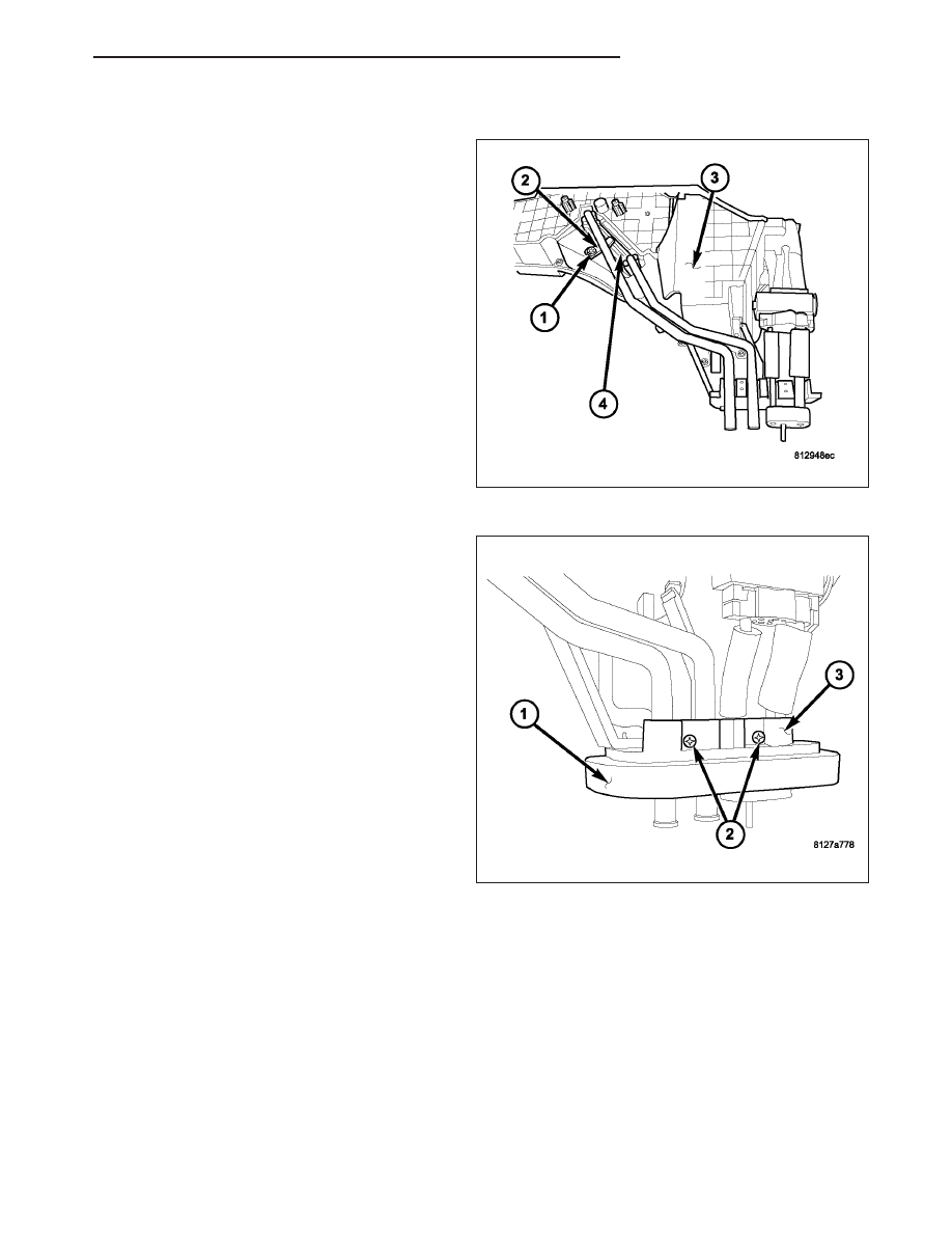
INSTALLATION
1. Install the rear heater core (4) into the side of the
rear HVAC housing (3). Make sure that the insula-
tor is properly installed.
2. Install the rear heater core retaining bracket (2).
3. Install the screw (1) that secures the rear heater
core retaining bracket to the rear HVAC housing.
Tighten the screw to 2 N·m (17 in. lbs.).
4. Install the outer halve of the rear heater core and
evaporator extension line flange (3).
5. Install the screws (2) that secure the two halves of
the rear heater core and evaporator extension line
flange together. Tighten the screws to 2 N·m (17 in.
lbs.).
6. Install the foam seal (1) to the rear heater core and
evaporator extension line flange.
7. Install the rear blend door actuator (Refer to 24 -
HEATING & AIR CONDITIONING/CONTROLS -
REAR/ACTUATOR-BLEND DOOR - INSTALLA-
TION).
NOTE: If the heater core is being replaced, flush
the cooling system (Refer to 7 - COOLING - STAN-
DARD PROCEDURE - COOLING SYSTEM CLEAN-
ING/REVERSE FLUSHING).
8. Install the rear HVAC housing (Refer to 24 - HEAT-
ING & AIR CONDITIONING/DISTRIBUTION - REAR/HOUSING-HVAC - INSTALLATION).
HB
PLUMBING - REAR
24 - 469