Dodge Durango (HB). Manual - part 1564


  Index      Dodge     Dodge Durango (HB) - service repair manual 2005 year


Search            


Content   ..  1562  1563  1564  1565   ..


Dodge Durango (HB). Manual - part 1564


REMOVAL

WARNING: Refer to the applicable warnings and cautions for this system before performing the following
operation (Refer to 24 - HEATING & AIR CONDITIONING/PLUMBING - FRONT - WARNINGS) and (Refer to 24
- HEATING & AIR CONDITIONING/PLUMBING - FRONT - CAUTIONS). Failure to follow the warnings and cau-
tions could result in possible personal injury or death.

1. Recover the refrigerant from the refrigerant system

(Refer to 24 - HEATING & AIR CONDITIONING/
PLUMBING - FRONT - STANDARD PROCEDURE
- REFRIGERANT SYSTEM RECOVERY).

2. Disconnect and isolate the negative battery cable.

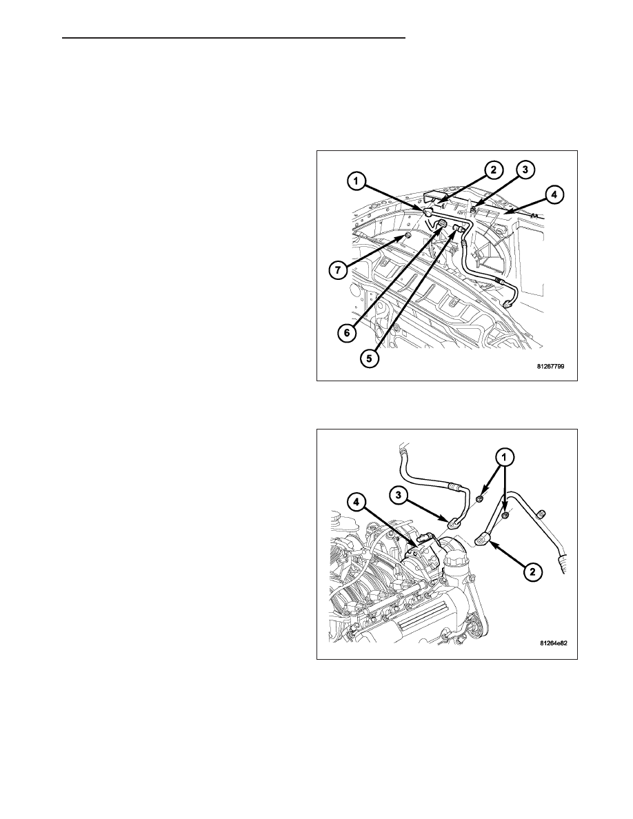
3. Disconnect the wire harness connector (6) from the

A/C pressure transducer (5).

4. If required, remove the A/C pressure transducer

from the A/C discharge line (1).

5. Remove the nut (7) that secures the A/C discharge

line to the A/C condenser (2).

6. Disconnect the A/C discharge line from the A/C

condenser and the retainer (3) located on the con-
denser fan shroud (4).

7. Remove the O-ring seal and gasket from the dis-

charge line fitting and discard.

8. Install plugs in, or tape over the discharge line fit-

ting and condenser port.

9. Remove the nut (1) that secures the A/C discharge

line (3) to the A/C compressor (4).

10. Disconnect the A/C discharge line from the A/C

compressor and remove and discard the O-ring
seal and gasket.

11. Install plugs in, or tape over the opened refriger-

ant line fitting and the compressor port.

12. Remove the A/C discharge line from the engine

compartment.

HB

PLUMBING - FRONT

24 - 449

INSTALLATION

1. Position the A/C discharge line into the engine

compartment.

2. Remove the tape or plugs from the opened dis-

charge line fitting and the compressor port.

3. Lubricate a new rubber O-ring seal with clean

refrigerant oil and install it and a new gasket onto
the discharge line fitting. Use only the specified
O-ring as it is made of a special material for the
R-134a system. Use only refrigerant oil of the type
recommended for the A/C compressor in the vehi-
cle.

4. Install the A/C discharge (3) line onto the A/C com-

pressor (4).

5. Install the nut (1) that secures the A/C discharge

line to the A/C compressor. Tighten the nut to 23
N·m (17 ft. lbs.).

6. Remove the tape or plugs from the opened dis-

charge line fitting (1) and the condenser port (2).

7. Lubricate a new rubber O-ring seal with clean

refrigerant oil and install it and a new gasket onto
the discharge line fitting. Use only the specified
O-ring as it is made of a special material for the
R-134a system. Use only refrigerant oil of the type
recommended for the A/C compressor in the vehi-
cle.

8. Install the A/C discharge line to the A/C condenser

and the retainer (3) located on the condenser fan
shroud.

9. Install the nut (7) that secures the A/C discharge

line to the A/C condenser. Tighten the nut to 22
N·m (16 ft. lbs.).

10. If removed, install the A/C pressure transducer (5)

onto the A/C discharge line.

11. Connect the wire harness connector (6) to the A/C

pressure transducer.

12. Connect the negative battery cable.

13. Evacuate the refrigerant system (Refer to 24 - HEATING & AIR CONDITIONING/PLUMBING -FRONT - STAN-

DARD PROCEDURE - REFRIGERANT SYSTEM EVACUATE).

14. Charge the refrigerant system (Refer to 24 - HEATING & AIR CONDITIONING/PLUMBING - FRONT - STAN-

DARD PROCEDURE - REFRIGERANT SYSTEM CHARGE).

24 - 450

PLUMBING - FRONT

HB

LINE-A/C LIQUID

DESCRIPTION

The liquid line is the refrigerant line that carries refrig-
erant from the A/C condenser to the A/C evaporator.
The liquid line is serviced in two sections. The front
section of the liquid line (1) connects between the A/C
condenser and the receiver/drier (2). The rear section
of the liquid line (3) connects between the receiver/
drier and the A/C expansion valve (7) and includes the
high side service port (5) and a tapping plate (8) that
secures the suction line (9) to the A/C expansion
valve. On models equipped with the rear heating-A/C
system, the rear section of the liquid line also includes
an extension tube that connects the liquid line to the
underbody lines (Refer to 24 - HEATING & AIR CON-
DITIONING/PLUMBING - REAR/LINE-A/C LIQUID -
DESCRIPTION).

CAUTION: Use only O-ring seals specified for the
vehicle. Failure to use the correct O-ring seal will
cause the refrigerant system connections to leak.

The liquid line has no serviceable parts except for the rubber O-ring seals, high-side service port valve, cap and
retainer clip (4). The O-ring seals used on the connections are made from a special type of rubber not affected by
R-134a refrigerant. The O-ring seals must be replaced whenever the liquid line is removed and installed.

If the liquid line is found to be leaking or is damaged, it must be replaced.

REMOVAL

WARNING: Refer to the applicable warnings and cautions for this system before performing the following
operation (Refer to 24 - HEATING & AIR CONDITIONING/PLUMBING - FRONT - WARNINGS) and (Refer to 24
- HEATING & AIR CONDITIONING/PLUMBING - FRONT - CAUTIONS). Failure to follow the warnings and cau-
tions could result in possible personal injury or death.

NOTE: The A/C liquid line is serviced in two sections. The front section connects between the A/C con-
denser and the receiver/drier. The rear section connects between the receiver/drier and the A/C expansion
valve. On models equipped with the rear heating-A/C system, the rear section of the A/C liquid line also
includes an extension tube that connects the liquid line to the underbody lines.

HB

PLUMBING - FRONT

24 - 451

FRONT SECTION

1. Recover the refrigerant from the refrigerant system

(Refer to 24 - HEATING & AIR CONDITIONING/
PLUMBING -FRONT - STANDARD PROCEDURE -
REFRIGERANT SYSTEM RECOVERY).

2. Disconnect and isolate the negative battery cable.

3. Remove the air cleaner housing (1) from the right

side of the engine compartment (Refer to 9 -
ENGINE/AIR

INTAKE

SYSTEM/AIR

CLEANER

HOUSING - REMOVAL).

4. Remove the bolt (1) that secures the front section

of the A/C liquid line (2) to the receiver/drier (3).

5. Disconnect the front section of the A/C liquid line

from the receiver/drier and remove and discard the
O-ring seal.

6. Install plugs in, or tape over the opened liquid line

fitting and receiver/drier port.

24 - 452

PLUMBING - FRONT

HB


Content   ..  1562  1563  1564  1565   ..