Content .. 1554 1555 1556 1557 ..
Dodge Durango (HB). Manual - part 1556
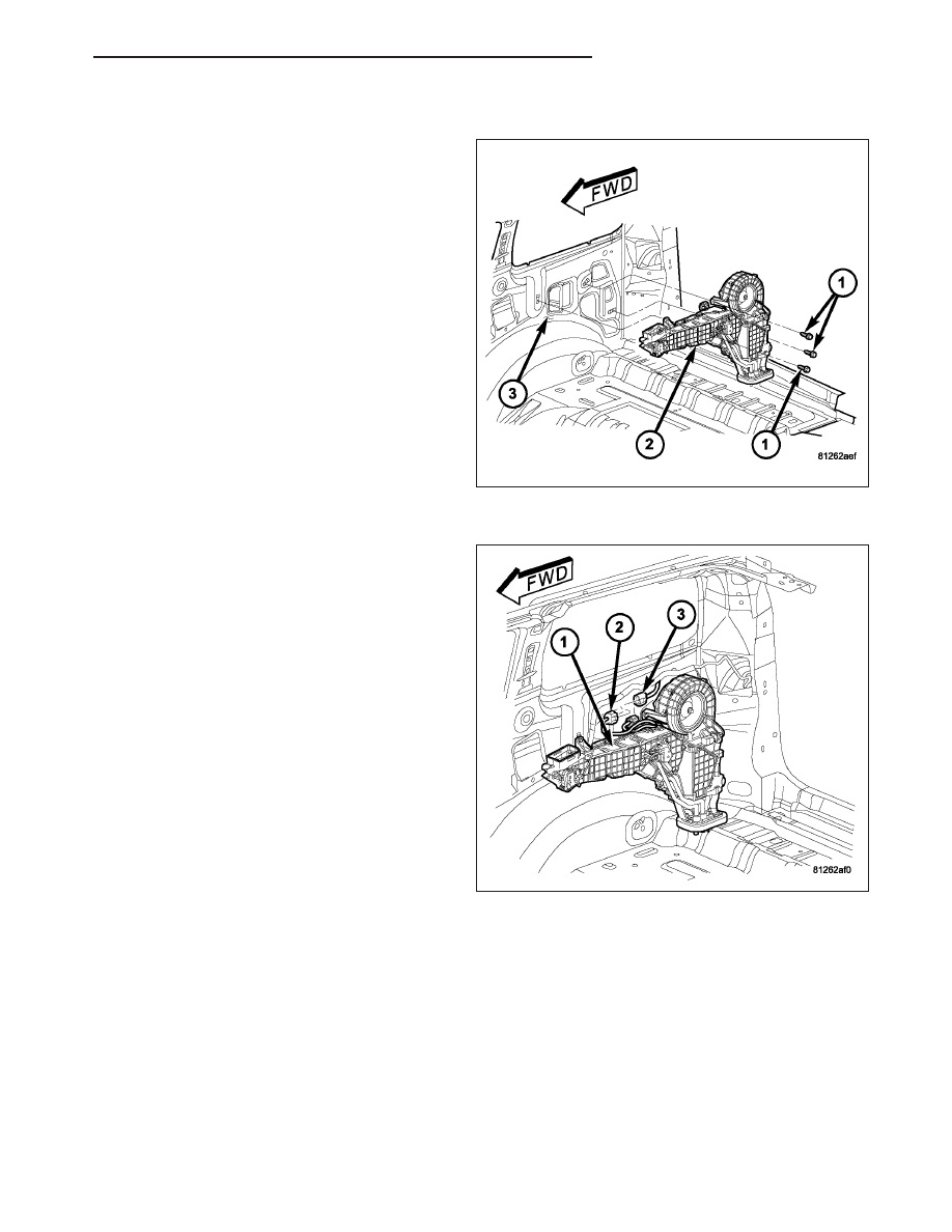
INSTALLATION
1. Position the rear HVAC housing (2) into the vehicle.
2. Install the three bolts (1) that secure the rear HVAC
housing to the rear interior quarter panel (3).
Tighten the bolts to 3 N·m (26 in. lbs.).
3. Connect the body wire harness connector (2) to the
rear HVAC wire harness connector (3).
4. Install the rear distribution ducts to the rear HVAC
housing (1) (Refer to 24 - HEATING & AIR CON-
DITIONING/DISTRIBUTION - REAR/DUCTS-DIS-
TRIBUTION - INSTALLATION).
5. Install the right rear quarter panel trim (Refer to 23
-
BODY/INTERIOR/QUARTER
PANEL TRIM
-
INSTALLATION).
HB
DISTRIBUTION - REAR
24 - 417