Dodge Durango (HB). Manual - part 1553


  Index      Dodge     Dodge Durango (HB) - service repair manual 2005 year


Search            


Content   ..  1551  1552  1553  1554   ..


Dodge Durango (HB). Manual - part 1553


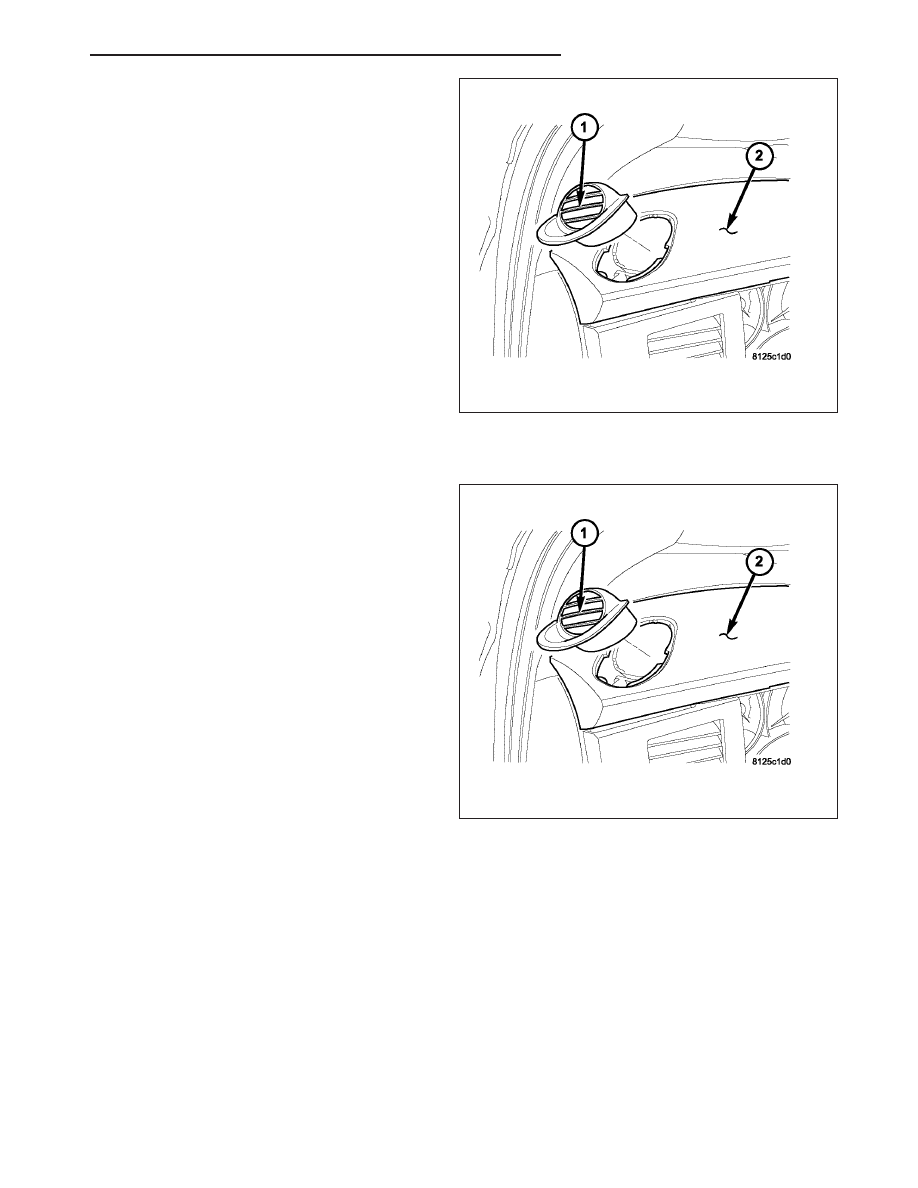
1. Using a trim stick or another suitable wide flat-

bladed tool, gently pry the instrument panel demis-
ter outlet(s) (1) out of the instrument panel top pad
(2) as required.

INSTALLATION - DEMISTER OUTLETS

1. Position the instrument panel demister outlet(s) (1)

onto the instrument panel top pad (2).

2. Gently push the demister outlet(s) into the top pad

until it snaps into place.

HB

DISTRIBUTION - FRONT

24 - 405

DISTRIBUTION - REAR

TABLE OF CONTENTS

page

page

DUCT-DISTRIBUTION

REMOVAL

. . . . . . . . . . . . . . . . . . . . . . . . . . . . 406

INSTALLATION

. . . . . . . . . . . . . . . . . . . . . . . . 407

HOUSING-HVAC

DESCRIPTION

. . . . . . . . . . . . . . . . . . . . . . . . 407

REMOVAL

. . . . . . . . . . . . . . . . . . . . . . . . . . . . 408

DISASSEMBLY

. . . . . . . . . . . . . . . . . . . . . . . . 409

ASSEMBLY

. . . . . . . . . . . . . . . . . . . . . . . . . . . 413

INSTALLATION

. . . . . . . . . . . . . . . . . . . . . . . . 417

MOTOR-BLOWER

DESCRIPTION

. . . . . . . . . . . . . . . . . . . . . . . . 418

OPERATION

. . . . . . . . . . . . . . . . . . . . . . . . . . 419

REMOVAL

. . . . . . . . . . . . . . . . . . . . . . . . . . . . 419

INSTALLATION

. . . . . . . . . . . . . . . . . . . . . . . . 419

OUTLET-AIR

DESCRIPTION

. . . . . . . . . . . . . . . . . . . . . . . . 420

REMOVAL

REAR CEILING AIR OUTLET

. . . . . . . . . . . . 421

REAR CEILING AIR OUTLET GRILLE

. . . . . 421

INSTALLATION

REAR CEILING AIR OUTLET

. . . . . . . . . . . . 422

REAR CEILING AIR OUTLET GRILLE

. . . . . 423

DUCT-DISTRIBUTION

REMOVAL

1. Remove the right interior quarter panel trim (Refer

to 23 - BODY/INTERIOR/QUARTER PANEL TRIM
- REMOVAL).

2. Remove the push-pin fasteners (1) that secure the

rear ceiling distribution duct (2) and the rear floor
distribution duct (3) to the right interior quarter
panel (4).

3. Disconnect the rear ceiling distribution duct from

the rear HVAC housing (5) by sliding the lower half
of the ceiling distribution duct into the upper half of
the ceiling distribution duct.

4. Disconnect the rear ceiling distribution duct from

the headliner duct and remove the ceiling distribu-
tion duct from the vehicle.

5. Disconnect the rear floor distribution duct from the

rear HVAC housing and remove the floor distribu-
tion duct from the vehicle.

24 - 406

DISTRIBUTION - REAR

HB

INSTALLATION

1. Connect the rear floor distribution duct (3) to the

rear HVAC housing (5).

2. Connect the rear ceiling distribution duct (2) to the

headliner duct and the rear HVAC housing. Make
sure that the rear ceiling distribution duct is fully
installed to ensure a good seal.

3. Install the push-pin fasteners (1) that secure the

rear ceiling distribution duct and the rear floor dis-
tribution duct to the right interior quarter panel (4).

4. Install the right interior quarter panel trim (Refer to

23 - BODY/INTERIOR/QUARTER PANEL TRIM -
INSTALLATION).

HOUSING-HVAC

DESCRIPTION

Models equipped with the rear heating-A/C system are equipped with a common rear heater and A/C housing (7)
that combines A/C and heating capabilities into a single unit mounted within the passenger compartment. The rear
heating-A/C system is a blend-air type system. A blend-air door (6) controls the amount of conditioned air that is
allowed to flow through, or around, the heater core (3). The rear A/C system is designed for the use of a non-CFC,
R-134a refrigerant and uses an A/C evaporator (2) to cool and dehumidify the incoming air prior to blending it with
the heated air. A temperature control determines the discharge air temperature by operating the blend door actuator

HB

DISTRIBUTION - REAR

24 - 407

(5) , which moves the blend-air door. This allows an almost immediate control of the output air temperature of the
system. The mode door actuator (8) operates the mode-air door (9) which directs the flow of the conditioned air out
the upper or lower air outlets, depending on the discharge air temperature selected. Both electric actuators are
connected to the vehicle electrical system by the HVAC wire harness (10). The rear blower motor (11) controls the
velocity of air flowing through the rear HVAC housing by spinning the blower wheel within the rear blower motor
housing (1) at the selected speed by use of the rear blower motor resistor block (4).

The rear HVAC housing must be removed from the vehicle and disassembled for service of the A/C evaporator,
heater core, mode-air door, blend-air door and blower motor.

REMOVAL

WARNING: Refer to the applicable warnings and cautions for this system before performing the following
operation (Refer to 24 - HEATING & AIR CONDITIONING/PLUMBING - FRONT - WARNINGS) and (Refer to 24
- HEATING & AIR CONDITIONING/PLUMBING - FRONT - CAUTIONS). Failure to follow the warnings and cau-
tions could result in possible personal injury or death.

NOTE: The rear HVAC housing must be removed from the vehicle and disassembled for service of the A/C
evaporator, heater core, mode-air door, blend-air door and blower motor.

1. Recover the refrigerant from the refrigerant system

(Refer to 24 - HEATING & AIR CONDITIONING/
PLUMBING - FRONT - STANDARD PROCEDURE
- REFRIGERANT SYSTEM RECOVERY).

2. Drain the engine cooling system (Refer to 7 -

COOLING - STANDARD PROCEDURE - COOL-
ING SYSTEM DRAIN).

3. Disconnect and isolate the negative battery cable.

4. Raise and support the vehicle.

5. Remove the nut (1) that secures the rear suction

line (2) and the rear liquid line (3) to the rear evap-
orator extension line tapping plate that extends
through the rear floor panel (4) behind the right
rear wheel housing.

6. Disconnect the rear suction line and liquid line from

the rear evaporator extension line tapping plate.

7. Remove the O-ring seals from the rear suction line

and liquid line fittings and discard.

8. Install plugs in, or tape over the opened refrigerant lines and tapping plate ports.

9. Disconnect the rear heater hoses (5) from the rear heater core tubes that extend through the rear floor panel

behind the right rear wheel housing.

24 - 408

DISTRIBUTION - REAR

HB


Content   ..  1551  1552  1553  1554   ..