Content .. 1550 1551 1552 1553 ..
Dodge Durango (HB). Manual - part 1552
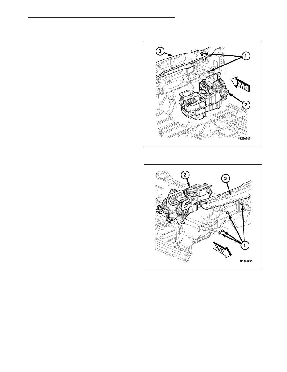
INSTALLATION
1. Position the HVAC housing (2) into the passenger
compartment with the mounting studs and the con-
densate drain tube in their proper mounting loca-
tions in the dash panel (3).
2. Loosely install the two bolts (1) that secure the
HVAC housing to the passenger compartment side
of the dash panel.
3. Install the four nuts (1) that secure the HVAC hous-
ing (2) to the engine compartment side of the dash
panel (3). Tighten the nuts to 7 N·m (62 in. lbs.).
4. Tighten the two bolts that secure the HVAC hous-
ing to the passenger compartment side of the dash
panel. Tighten the bolt(s) to 3 N·m (26 in. lbs.).
5. Connect the intermediate floor distribution duct to
front floor distribution duct.
6. Install the instrument panel (Refer to 23 - BODY/
INSTRUMENT
PANEL/INSTRUMENT
PANEL
ASSEMBLY - INSTALLATION).
7. Remove previously installed plugs or caps and
reconnect the heater hoses to the heater core
tubes.
8. Remove previously installed plugs or caps and
reconnect the suction line and liquid line to the
expansion valve (Refer to 24 - HEATING & AIR
CONDITIONING/PLUMBING
-
FRONT/LINE-A/C
LIQUID - INSTALLATION).
9. Reconnect the negative battery cable.
10. If the heater core is being replaced, flush the cooling system (Refer to 7 - COOLING - STANDARD PROCE-
DURE - COOLING SYSTEM CLEANING/REVERSE FLUSHING).
11. Refill the engine cooling system (Refer to 7 - COOLING - STANDARD PROCEDURE - COOLING SYSTEM
REFILL).
12. Evacuate the refrigerant system (Refer to 24 - HEATING & AIR CONDITIONING/PLUMBING - FRONT - STAN-
DARD PROCEDURE - REFRIGERANT SYSTEM EVACUATE).
13. Charge the refrigerant system (Refer to 24 - HEATING & AIR CONDITIONING/PLUMBING - FRONT - STAN-
DARD PROCEDURE - REFRIGERANT SYSTEM CHARGE).
HB
DISTRIBUTION - FRONT
24 - 401