Content .. 1539 1540 1541 1542 ..
Dodge Durango (HB). Manual - part 1541
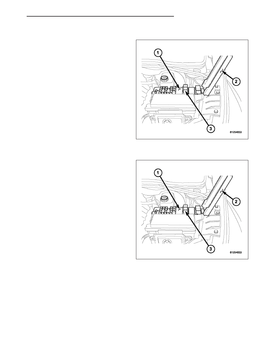
REMOVAL
1. Disconnect and isolate the negative battery cable.
2. Locate the power distribution center (PDC) (1).
3. Open the PDC cover (2).
NOTE: Refer to the fuse and relay map on the
inside of the PDC cover for A/C clutch relay loca-
tion.
4. Remove the A/C clutch relay (3) from the PDC.
INSTALLATION
NOTE: Refer to the fuse and relay map on the
inside of the PDC cover for A/C clutch relay loca-
tion.
1. Position the A/C clutch relay (3) into the proper
receptacle of the PDC (1).
2. Align the A/C clutch relay terminals with the termi-
nal cavities in the PDC receptacle and push down
firmly on the relay until the terminals are fully
seated.
3. Close the PDC cover (2).
4. Reconnect the negative battery cable.
HB
CONTROLS - FRONT
24 - 357