Dodge Durango (HB). Manual - part 1523


  Index      Dodge     Dodge Durango (HB) - service repair manual 2005 year


Search            


Content   ..  1521  1522  1523  1524   ..


Dodge Durango (HB). Manual - part 1523


B1070–REAR BLOWER CONTROL CIRCUIT HIGH (ATC) (CONTINUED)

5.

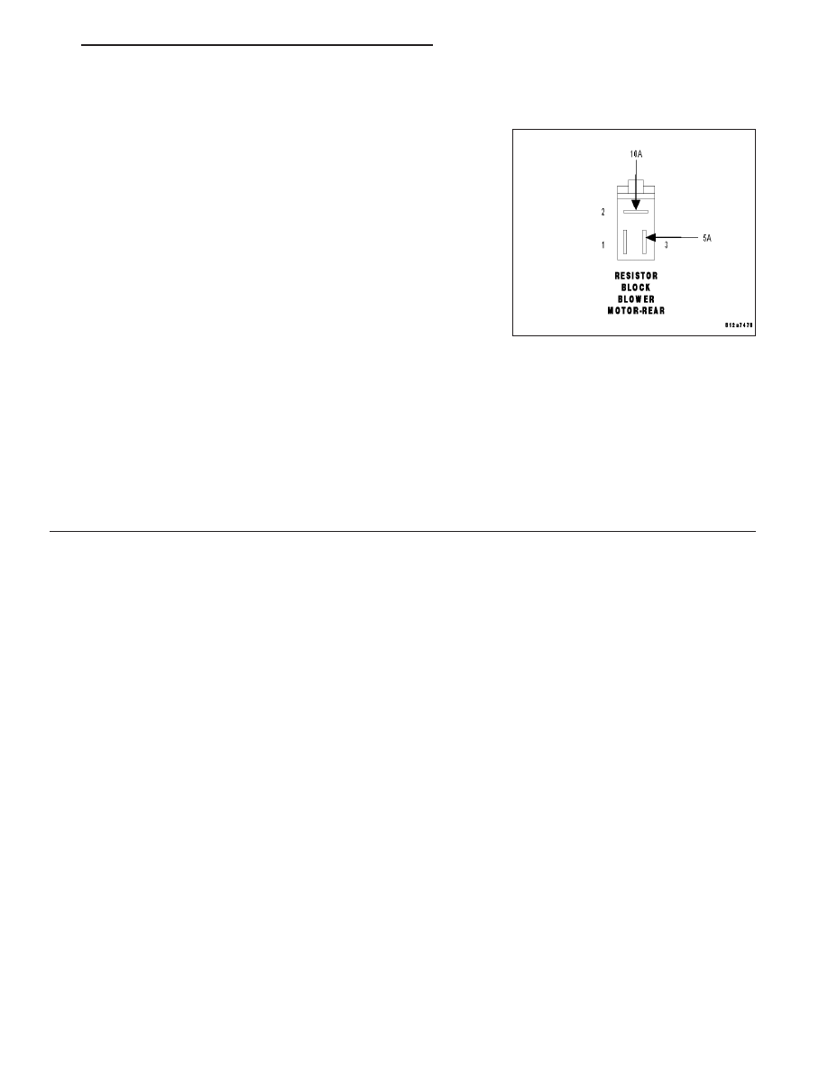
CHECK REAR BLOWER MOTOR RESISTOR BLOCK FOR CAUSE OF HIGH AMPERAGE DRAW

Turn the ignition off.

Remove the 20 amp fused jumper wire from the (C153) Rear Blower
High Speed circuit in the Rear Blower Motor Harness connector.

Reconnect the Rear Blower Motor Resistor Block harness connector.

Connect a 10 amp fused jumper wire between ground and the (C152)
Rear Blower Medium Speed circuit in the Rear Blower Motor Resistor
Block harness connector.

Start the engine. The rear blower motor should run with out blowing
the fuse.

Turn the ignition off.

Remove the 10 amp fused jumper wire from the (C152) Rear Blower
Medium Speed circuit in the Rear Blower Motor Resistor Block har-
ness connector.

Connect a 5 amp fused jumper wire between ground and the (C151) Rear Blower Low Speed circuit in the Rear
Blower Motor Resistor Block harness connector.

Start the engine. The rear blower motor should run with out blowing the fuse.

Does the rear blower motor run with out blowing either of the fuses?

Yes

>> Replace the A/C Heater Control in accordance with the Service Information.

Perform BODY VERIFICATION TEST - VER 1.

No

>> Replace the Rear Blower Motor Resistor Block in accordance with the Service Information.

Perform BODY VERIFICATION TEST - VER 1.

HB

HVAC - ELECTRICAL DIAGNOSTICS

24 - 285

B1079–CLIMATE CONTROL COOL DOWN TEST EXCESSIVE TIME (ATC & MTC)

For a complete wiring diagram Refer to Section 8W.

When Monitored:
When the Cooldown Test is executed.

Set Condition:
If the A/C system is unable to lower the evaporator temperature 11.11°C (20°F) within one minute.

Possible Causes

EVAPORATOR TEMPERATURE SENSOR CIRCUITS

EVAPORATOR TEMPERATURE SENSOR

OTHER HVAC SYSTEM FAULTS PRESENT

POWERTRAIN SYSTEM FAULTS PRESENT

Theory of Operation

The Cooldown Test checks A/C system performance based on Evaporator Temperature Sensor input. The main cri-
teria is to lower evaporator temperature 11.11°C (20°F) within one minute. Before starting the test, the evaporator
temperature must be above 18.3°C (65°F) and for Manual Temperature Control systems the front blower speed
must be set to high speed. When the test is running, A/C Select and A/C Request will be on and the A/C status
indicator will flash. When the test is complete, the scan tool will display one or more test status messages to indi-
cate the outcome of the Cooldown Test. A Successful Cooldown – Test Passed status message indicates that the
main test criteria was met. A DTC Set During Routine – Test Not Passed status message indicates that the A/C
system is unable to lower the evaporator temperature 11.11°C (20°F) within one minute. A Conditions Too Cold –
Test Not Run status message indicates that the evaporator temperature was below 18.3°C (65°F) when starting the
Cooldown Test. A Blowers Not On High – Test Not Run status message indicates that either the front blower speed
was not set to high speed prior to starting the Cooldown Test or the front blower speed was changed from high
speed to another setting after starting the Cooldown test. A Refrigerant Temperature Sensor Error status message
indicates that a fault occurred with the Evaporator Temperature Sensor/sensor circuits. A No Results Stored/Test Not
Complete status message indicates that the power was cycled while the test was running.

Diagnostic Test

1.

CHECK FOR DTCs IN THE A/C HEATER CONTROL MODULE

Turn the ignition on.

With the scan tool, select ECU View.

With the scan tool, select HVAC.

Are any DTCs present in the A/C Heater Control Module?

Yes

>> Diagnose and Repair the DTC(s). Refer to the Table of Contents in this Section for a complete list of

HVAC related symptoms. Rerun the Cooldown Test after the repair is complete.

Perform BODY VERIFICATION TEST – VER 1.

No

>> Go To 2

24 - 286

HVAC - ELECTRICAL DIAGNOSTICS

HB

B1079–CLIMATE CONTROL COOL DOWN TEST EXCESSIVE TIME (ATC & MTC) (CONTINUED)

2.

CHECK FOR DTCs IN THE PCM

With the scan tool, select PCM.

Are any DTCs present in the PCM?

Yes

>> Diagnose and repair the DTC(s). (Refer to 9 - ENGINE - DIAGNOSIS AND TESTING) for PCM DTCs.

Rerun the Cooldown Test after the repair is complete.

Perform BODY VERIFICATION TEST – VER 1.

No

>> Refer to the Service Information for additional Cooldown Test related diagnostic information and testing

procedures. Rerun the Cooldown Test after the repair is complete.

Perform BODY VERIFICATION TEST – VER 1.

HB

HVAC - ELECTRICAL DIAGNOSTICS

24 - 287

B1080–AUXILIARY COOLANT PUMP CONTROL CIRCUIT OPEN (ATC)

24 - 288

HVAC - ELECTRICAL DIAGNOSTICS

HB


Content   ..  1521  1522  1523  1524   ..