Dodge Durango (HB). Manual - part 1510


  Index      Dodge     Dodge Durango (HB) - service repair manual 2005 year


Search            


Content   ..  1508  1509  1510  1511   ..


Dodge Durango (HB). Manual - part 1510


B1053–REAR BLEND DOOR CONTROL CIRCUIT LOW (MTC) (CONTINUED)

4.

CHECK (C54) REAR BLEND DOOR DRIVER CIRCUIT FOR A SHORT TO (C154) REAR COMMON DOOR
DRIVER CIRCUIT

Disconnect the Rear Blend Door Actuator harness connector.

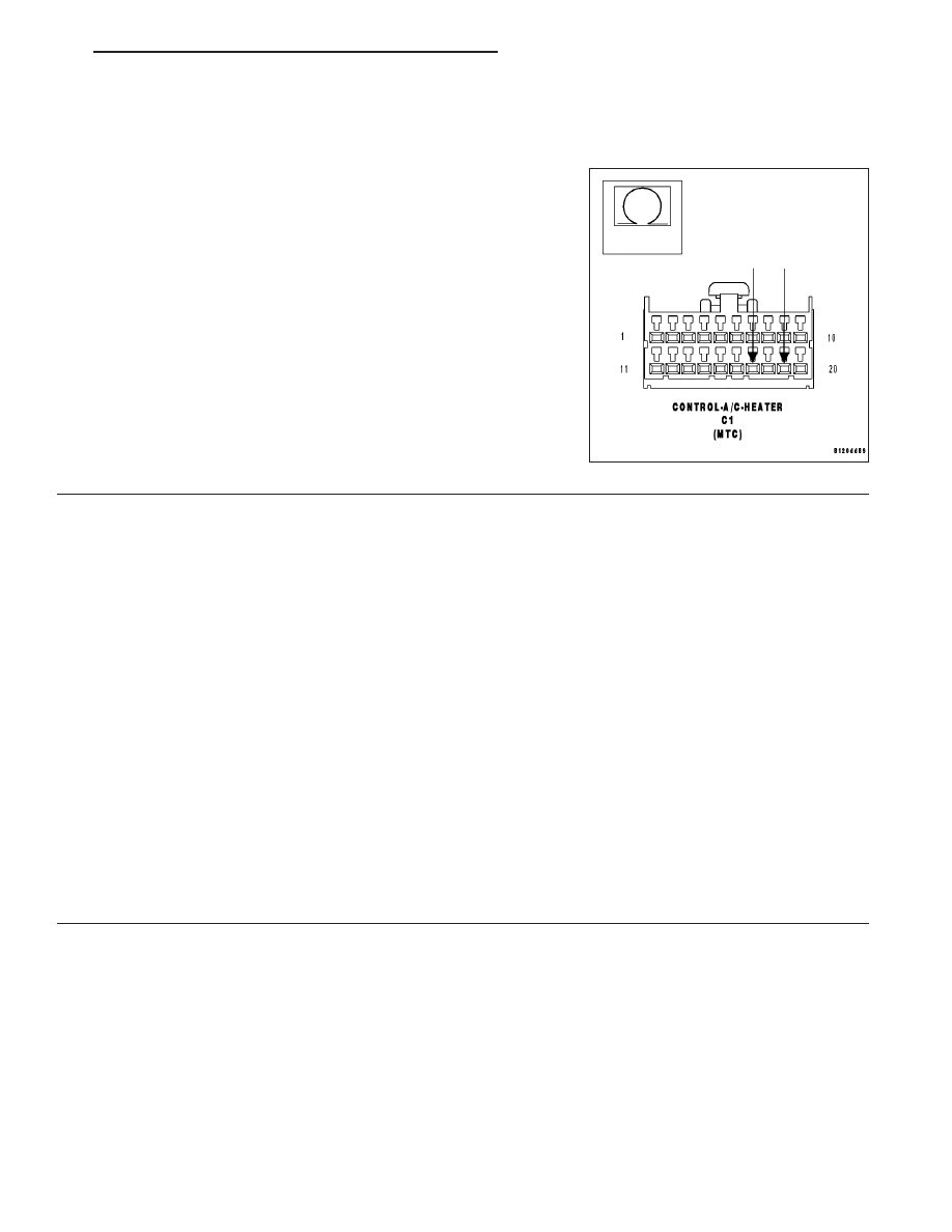
Measure the resistance between the (C54) Rear Blend Door Driver cir-
cuit and the (C154) Rear Common Door Driver circuit in the A/C
Heater Control C1 harness connector.

Is the resistance below 10k ohms?

Yes

>> Repair the (C54) Rear Blend Door Driver circuit for a short

to the (C154) Rear Common Door Driver circuit.

Perform BODY VERIFICATION TEST - VER 1.

No

>> Replace the Rear Blend Door Actuator in accordance with

the Service Information.

Perform BODY VERIFICATION TEST - VER 1.

5.

RUN THE ACTUATOR DTC DETECTION TEST

Reconnect the A/C Heater Control C1 harness connector.

Turn the ignition on.

With the scan tool, erase HVAC DTCs.

Turn the ignition off, wait 10 seconds, and then turn the ignition on.

With the scan tool, select System Tests and then select Actuator DTC Detection. When the test is complete, select
View DTCs.

Does the scan tool only display: B1053–REAR BLEND DOOR CONTROL CIRCUIT LOW?

Yes

>> Replace the A/C Heater Control in accordance with the Service Information.

Perform BODY VERIFICATION TEST - VER 1.

No, Other DTC(s) Displayed

Diagnose and repair the other DTC(s). If multiple DTCs are present, beginning with the common cir-
cuits, diagnose and repair all short high DTCs and then all short low DTCs. Refer to the Table of Con-
tents in this Section for a complete list of all HVAC related symptoms.

No, And No Other DTCs Displayed

Using the wiring diagram as a guide, inspect the wiring and connectors for conditions causing an inter-
mittent short. Repair as necessary.

Perform BODY VERIFICATION TEST - VER 1.

HB

HVAC - ELECTRICAL DIAGNOSTICS

24 - 233

B1054–REAR BLEND DOOR CONTROL CIRCUIT HIGH (ATC)

24 - 234

HVAC - ELECTRICAL DIAGNOSTICS

HB

B1054–REAR BLEND DOOR CONTROL CIRCUIT HIGH (ATC) (CONTINUED)

For the Automatic Temperature Control (ATC) circuit diagram (Refer to 24 - HEATING & AIR CONDITIONING -
SCHEMATICS AND DIAGRAMS).

For a complete wiring diagram Refer to Section 8W.

When Monitored:
When the Actuator DTC Detection Test is executed.

Set Condition:
If the (C53) Rear Mode Door Driver circuit, the (C54) Rear Blend Door Driver circuit, the (C801) Mode Door 2
Driver circuit, the (C154) Rear Common Door Driver circuit, or the (C808) Common Door Driver 3 circuit is
shorted to voltage.

Possible Causes

(C53) REAR MODE DOOR DRIVER CIRCUIT SHORTED TO VOLTAGE

(C54) REAR BLEND DOOR DRIVER CIRCUIT SHORTED TO VOLTAGE

(C801) MODE DOOR 2 DRIVER CIRCUIT SHORTED TO VOLTAGE

(C154) REAR COMMON DOOR DRIVER CIRCUIT SHORTED TO VOLTAGE

(C808) COMMON DOOR DRIVER 3 CIRCUIT SHORTED TO VOLTAGE

A/C HEATER CONTROL

Theory of Operation

The A/C Heater Control drives the Rear Mode Door Actuator via the (C53) Rear Mode Door Driver circuit and the
(C154) Rear Common Door Driver circuit. The A/C Heater Control drives the Rear Blend Door Actuator via the
(C54) Rear Blend Door Driver circuit and the (C154) Rear Common Door Driver circuit. In addition, the Rear Mode
Door Actuator, the Rear Blend Door Actuator, and the Mode Door 2 (Floor to Defrost) Actuator share a driver inside
the A/C Heater Control. Due to the shared circuitry similar DTCs can set at the same time for multiple actuators
depending upon the type of short, its location, and the direction the actuator is moving when the short is present.

Diagnostic Test

1.

CHECK (C53) REAR MODE DOOR DRIVER CIRCUIT, (C54) REAR BLEND DOOR DRIVER CIRCUIT, (C808)
COMMON DOOR DRIVER 3 CIRCUIT, (C154) REAR COMMON DOOR DRIVER CIRCUIT, & (C801) MODE
DOOR 2 DRIVER CIRCUIT FOR A SHORT TO VOLTAGE

Turn the ignition off.

Disconnect the A/C Heater Control C1 harness connector.

Turn the ignition on.

Measure the voltage of the (C53) Rear Mode Door Driver circuit.

Measure the voltage of the (C54) Rear Blend Door Driver circuit.

Measure the voltage of the (C808) Common Door Driver 3 Circuit.

Measure the voltage of the (C154) Rear Common Door Driver circuit.

Measure the voltage of the (C801) Mode Door 2 Driver circuit.

Is the voltage above 0.2 volts on any of the circuits?

Yes

>> Repair the circuit(s) with voltage above 0.2 volts for a

short to voltage.

Perform BODY VERIFICATION TEST - VER 1.

No

>> Go To 2

HB

HVAC - ELECTRICAL DIAGNOSTICS

24 - 235

B1054–REAR BLEND DOOR CONTROL CIRCUIT HIGH (ATC) (CONTINUED)

2.

RUN THE ACTUATOR DTC DETECTION TEST

Turn the ignition off.

Reconnect the A/C Heater Control C1 harness connector.

Turn the ignition on.

With the scan tool in HVAC, select System Tests and then select Actuator DTC Detection. When the test is com-
plete, select View DTCs.

Does the scan tool display: B1054–REAR BLEND DOOR CONTROL CIRCUIT HIGH?

Yes

>> Replace the A/C Heater Control in accordance with the Service Information.

Perform BODY VERIFICATION TEST - VER 1.

No, Other DTC(s) Displayed

Diagnose and repair the other DTC(s). If multiple DTCs are present, beginning with the common cir-
cuits, diagnose and repair all short high DTCs and then all short low DTCs. Refer to the Table of Con-
tents in this Section for a complete list of all HVAC related symptoms.

No, And No Other DTCs Displayed

Using the wiring diagram as a guide, inspect the wiring and connectors for conditions causing an inter-
mittent short. Repair as necessary.

Perform BODY VERIFICATION TEST - VER 1.

24 - 236

HVAC - ELECTRICAL DIAGNOSTICS

HB


Content   ..  1508  1509  1510  1511   ..