Dodge Durango (HB). Manual - part 1396


  Index      Dodge     Dodge Durango (HB) - service repair manual 2005 year


Search            


Content   ..  1394  1395  1396  1397   ..


Dodge Durango (HB). Manual - part 1396


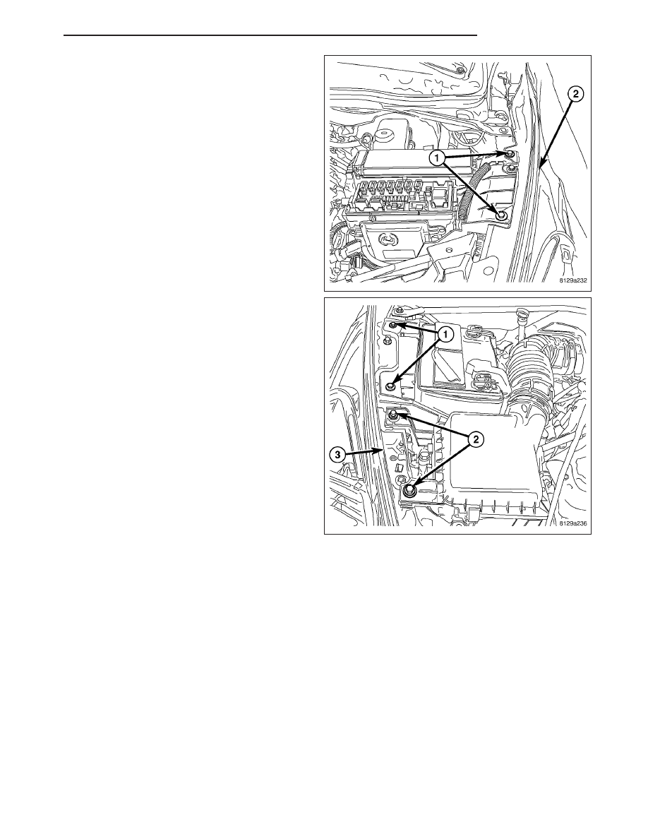
11. When installing the left side fender, install the

power distribution center bolts (1) to the FESM (2)
and tighten to 11 N·m (100 in. lbs.).

12. When installing the right side fender, install the

battery tray bolts and tighten to 11 N·m (100 in.
lbs.).

13. Install the air cleaner mounting bolts and tighten

to 10 N·m (85 in. lbs.).

14. Install the cowl grille. (Refer to 23 - BODY/EXTE-

RIOR/COWL GRILLE AND SCREEN - INSTALLA-
TION)

15. Install the wheelhouse splash shield. (Refer to 23

-

BODY/EXTERIOR/FRONT

WHEELHOUSE

SPLASH SHIELD - DESCRIPTION)

16. Install the headlight assembly. (Refer to 8 - ELEC-

TRICAL/LAMPS/LIGHTING - EXTERIOR/HEAD-
LAMP UNIT - INSTALLATION)

17. Install the grille. (Refer to 23 - BODY/EXTERIOR/

GRILLE - INSTALLATION)

HB

EXTERIOR

23 - 97

INSTRUMENT PANEL

TABLE OF CONTENTS

page

page

INSTRUMENT PANEL

WARNING

RESTRAINT SYSTEM

. . . . . . . . . . . . . . . . . . 98

BEZEL-CLUSTER

REMOVAL

. . . . . . . . . . . . . . . . . . . . . . . . . . . . . 99

INSTALLATION

. . . . . . . . . . . . . . . . . . . . . . . . 100

GRILLE-DEFROSTER

REMOVAL

. . . . . . . . . . . . . . . . . . . . . . . . . . . . 101

INSTALLATION

. . . . . . . . . . . . . . . . . . . . . . . . 102

ASSEMBLY-INSTRUMENT PANEL

REMOVAL

. . . . . . . . . . . . . . . . . . . . . . . . . . . . 102

INSTALLATION

. . . . . . . . . . . . . . . . . . . . . . . . 110

COVER-STEERING COLUMN OPENING

REMOVAL

. . . . . . . . . . . . . . . . . . . . . . . . . . . . 118

INSTALLATION

. . . . . . . . . . . . . . . . . . . . . . . . 119

BEZEL-CENTER

REMOVAL

. . . . . . . . . . . . . . . . . . . . . . . . . . . . 120

INSTALLATION

. . . . . . . . . . . . . . . . . . . . . . . . 121

INSTRUMENT PANEL

WARNING

RESTRAINT SYSTEM

WARNING: To avoid personal injury or death, during and following any seat belt or child restraint anchor
service, carefully inspect all seat belts, buckles, mounting hardware, retractors, tether straps, and anchors
for proper installation, operation, or damage. Replace any belt that is cut, frayed, or torn. Straighten any
belt that is twisted. Tighten any loose fasteners. Replace any belt that has a damaged or inoperative buckle
or retractor. Replace any belt that has a bent or damaged latch plate or anchor plate. Replace any child
restraint anchor or the unit to which the anchor is integral that has been bent or damaged. Never attempt to
repair a seat belt or child restraint component. Always replace damaged or faulty seat belt and child
restraint components with the correct, new and unused replacement parts listed in the daimlerchrysler
mopar parts catalog.

WARNING: To avoid personal injury or death, on vehicles equipped with airbags, disable the supplemental
restraint system before attempting any steering wheel, steering column, airbag, occupant classification sys-
tem, seat belt tensioner, impact sensor, or instrument panel component diagnosis or service. Disconnect
and isolate the battery negative (ground) cable, then wait two minutes for the system capacitor to discharge
before performing further diagnosis or service. This is the only sure way to disable the supplemental
restraint system. Failure to take the proper precautions could result in accidental airbag deployment.

WARNING: To avoid personal injury or death on vehicles equipped with airbags, before performing any
welding operations disconnect and isolate the battery negative (ground) cable and disconnect all wire har-
ness connectors from the airbag control module (acm). Failure to take the proper precautions could result
in accidental airbag deployment and other possible damage to the supplemental restraint system circuits
and components.

WARNING: To avoid personal injury or death, do not attempt to dismantle an airbag unit or tamper with its
inflator. Do not puncture, incinerate, or bring into contact with electricity. Do not store at temperatures
exceeding 93° c (200° f). An airbag inflator unit may contain sodium azide and potassium nitrate. These
materials are poisonous and extremely flammable. Contact with acid, water, or heavy metals may produce
harmful and irritating gases (sodium hydroxide is formed in the presence of moisture) or combustible com-
pounds. An airbag inflator unit may also contain a gas canister pressurized to over 2500 psi.

23 - 98

INSTRUMENT PANEL

HB

WARNING: To avoid personal injury or death, when handling a seat belt tensioner retractor, proper care
should be exercised to keep fingers out from under the retractor cover and away from the seat belt webbing
where it exits from the retractor cover.

WARNING: To avoid personal injury or death, replace all restraint system components only with parts spec-
ified in the daimlerchrysler mopar parts catalog. Substitute parts may appear interchangeable, but internal
differences may result in inferior occupant protection.

WARNING: To avoid personal injury or death, the fasteners, screws, and bolts originally used for the
restraint system components must never be replaced with any substitutes. These fasteners have special
coatings and are specifically designed for the restraint system. Any time a new fastener is needed, replace
it with the correct fasteners provided in the service package or specified in the daimlerchrysler mopar parts
catalog.

WARNING: To avoid personal injury or death, when a steering column has an airbag unit attached, never
place the column on the floor or any other surface with the steering wheel or airbag unit face down.

BEZEL-CLUSTER

REMOVAL

1. Before proceeding with the following repair proce-

dure, review all warnings and cautions. (Refer to
23 - BODY/INSTRUMENT PANEL - WARNING)

2. Remove the steering column opening cover. (Refer

to 23 - BODY/INSTRUMENT PANEL/STEERING
COLUMN OPENING COVER - REMOVAL)

3. Remove the screws (1) and using a trim stick

C-4755 or equivalent, separate the cluster bezel
from the instrument panel.

HB

INSTRUMENT PANEL

23 - 99

4. Disconnect the electrical connectors.

INSTALLATION

1. Before proceeding with the following repair proce-

dure, review all warnings and cautions. (Refer to
23 - BODY/INSTRUMENT PANEL - WARNING)

2. Connect the electrical connectors.

3. Position the bezel (2) onto the instrument panel

and seat fully.

4. Install the screws (1).

5. Install the steering column opening cover. (Refer to

23

-

BODY/INSTRUMENT

PANEL/STEERING

COLUMN OPENING COVER - INSTALLATION)

23 - 100

INSTRUMENT PANEL

HB


Content   ..  1394  1395  1396  1397   ..