Content .. 1395 1396 1397 1398 ..
Dodge Durango (HB). Manual - part 1397
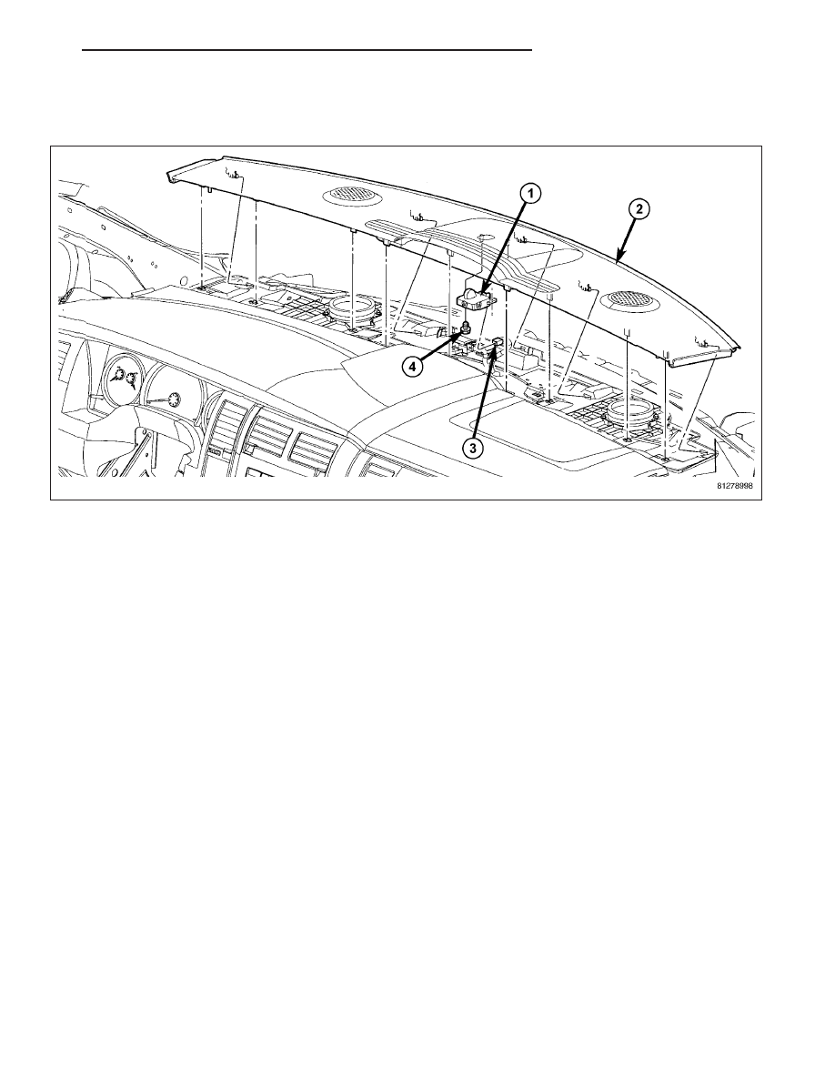
GRILLE-DEFROSTER
REMOVAL
1. Before proceeding with the following repair procedure, review all warnings and cautions. (Refer to 23 - BODY/
INSTRUMENT PANEL - WARNING)
2. Using a trim stick C-4755 or equivalent, remove the drivers side a-pillar trim.
3. Open the trim covers in the passenger side a-pillar grab handle and remove the bolts.
4. Remove the right a-pillar trim panel.
5. Using a trim stick C-4755 or equivalent, remove the instrument panel defroster grille.
6. Disconnect the sensor electrical connector (2).
7. Remove the screw (4) and remove the sun sensor (1).
HB
INSTRUMENT PANEL
23 - 101